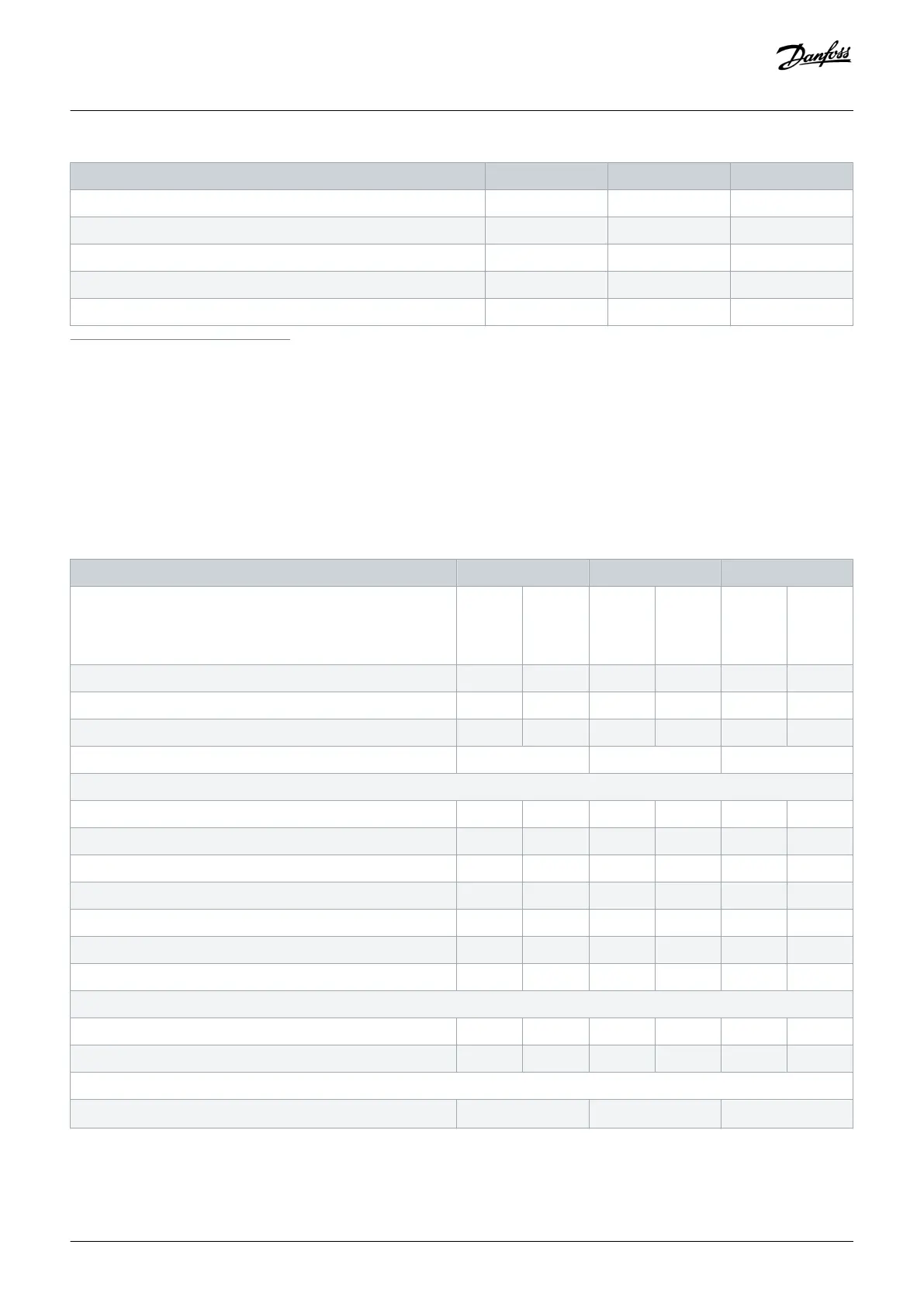
FC 202 N110 N132 N160
Heat sink overtemperature trip [°C (°F)] 110 (230) 110 (230) 110 (230)
Control card overtemperature trip [°C (°F)] 75 (167) 75 (167) 75 (167)
PHF overtemperature trip [°C (°F)] 150 (302) 150 (302) 150 (302)
dU/dt filter overtemperature trip [°C (°F)] 150 (302) 150 (302) 150 (302)
Sine-wave filter overtemperature trip [°C (°F)] 150 (302) 150 (302) 150 (302)
1
Typical power loss is at normal conditions and expected to be within ±15% (tolerance relates to variety in voltage and cable conditions.) These values are based on a typical motor
efficiency (IE/IE3 border line). Lower efficiency motors add to the power loss in the drive. Applies to dimensioning of drive cooling. If the switching frequency is higher than the default
setting, the power losses can increase. LCP and typical control card power consumptions are included. For power loss data according to EN 50598-2, refer to drives.danfoss.com/
knowledge-center/energy-efficiency-directive/#/. Options and customer load can add up to 30 W to the losses, though usually a fully loaded control card and options for slots A and B
each add only 4 W.
2
Measured using 5 m (16.4 ft) shielded motor cables at rated load and rated frequency. Efficiency measured at nominal current. For energy efficiency class, see the Ambient Conditions
section. For part load losses, see drives.danfoss.com/knowledge-center/energy-efficiency-directive/#/.
3
See also Input Power Option Losses.
4
If using an output filter, the output frequency is limited further. See the Motor Output (U, V, W) section.
Table 79: Electrical Data, Mains Supply 3x380–480 V AC
FC 202 N200 N250 N315
High/normal overload
High overload=150% or 160% torque for a duration of 60 s.
Normal overload=110% torque for a duration of 60 s.
HO NO HO NO HO NO
Typical shaft output at 400 V [kW] 160 200 200 250 250 315
Typical shaft output at 460 V [hp] 250 300 300 350 350 450
Typical shaft output at 480 V [kW] 200 250 250 315 315 355
Enclosure size D10h D10h D10h
Output current (3-phase)
Continuous (at 400 V) [A] 315 395 395 480 480 588
Intermittent (60 s overload) (at 400 V) [A] 473 435 593 528 720 647
Continuous (at 460/480 V) [A] 302 361 361 443 443 535
Intermittent (60 s overload) (at 460/480 V) [A] 453 397 542 487 665 589
Continuous kVA (at 400 V) [kVA] 218 274 274 333 333 407
Continuous kVA (at 460 V) [kVA] 241 288 288 353 353 426
Continuous kVA (at 480 V) [kVA] 262 313 313 384 384 463
Maximum input current
Continuous (at 400 V) [A] 304 381 381 463 463 567
Continuous (at 460/480 V) [A] 291 348 348 427 427 516
Maximum number and size of cables per phase
- Mains [mm
2
(AWG)]
2x185 (2x350 mcm) 2x185 (2x350 mcm) 2x185 (2x350 mcm)
Specifications
Operating Guide | VLT® AQUA Drive FC 202
AQ262141056213en-000101 / 130R0882 | 161
Danfoss A/S © 2018.10

 Loading...


