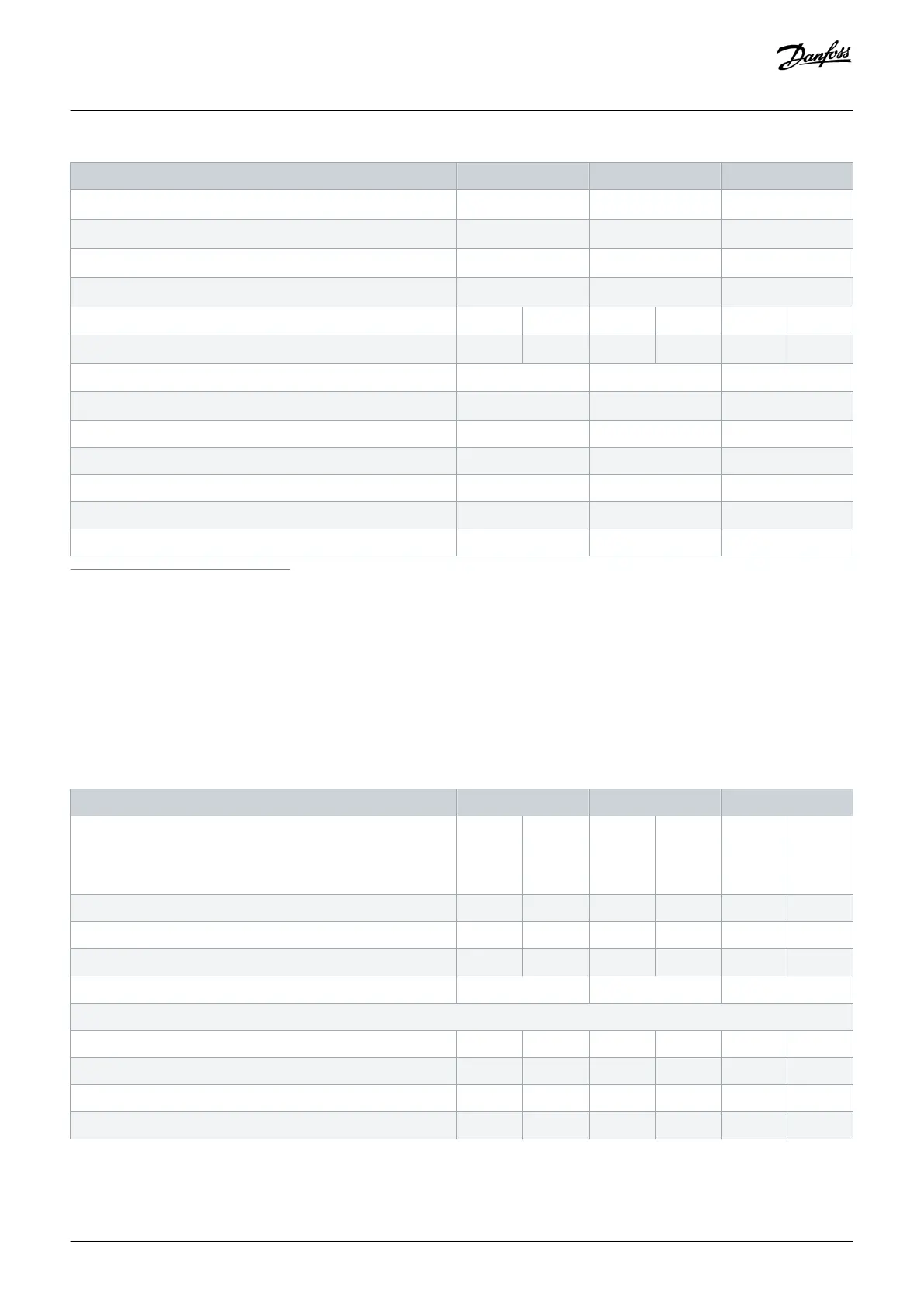
FC 202 N200 N250 N315
- Mains with disconnect [mm
2
(AWG)]
2x185 (2x350 mcm) 2x185 (2x350 mcm) 2x185 (2x350 mcm)
- Mains with fusible disconnect [mm
2
(AWG)]
2x185 (2x350 mcm) 2x185 (2x350 mcm) 2x185 (2x350 mcm)
- Mains with contactor [mm
2
(AWG)]
2x185 (2x350 mcm) 2x185 (2x350 mcm) 2x185 (2x350 mcm)
- Mains [mm
2
(AWG)]
2x185 (2x350 mcm) 2x185 (2x350 mcm) 2x185 (2x350 mcm)
Drive module power loss at 400 V [W]
(1) (2) (3)
3093 4116 4039 5137 5005 6674
Drive module power loss at 460 V [W]
(1) (2) (3)
2872 3569 3575 4566 4458 5714
Drive efficiency
(2)
0.98 0.98 0.98
Output frequency [Hz]
(4)
0–590 0–590 0–590
Heat sink overtemperature trip [°C (°F)] 110 (230) 110 (230) 110 (230)
Control card overtemperature trip [°C (°F)] 80 (176) 80 (176) 80 (176)
PHF overtemperature trip [°C (°F)] 150 (302) 150 (302) 150 (302)
dU/dt filter overtemperature trip [°C (°F)] 150 (302) 150 (302) 150 (302)
Sine-wave filter overtemperature trip [°C (°F)] 150 (302) 150 (302) 150 (302)
1
Typical power loss is at normal conditions and expected to be within ±15% (tolerance relates to variety in voltage and cable conditions.) These values are based on a typical motor
efficiency (IE/IE3 border line). Lower efficiency motors add to the power loss in the drive. Applies to dimensioning of drive cooling. If the switching frequency is higher than the default
setting, the power losses can increase. LCP and typical control card power consumptions are included. For power loss data according to EN 50598-2, refer to drives.danfoss.com/
knowledge-center/energy-efficiency-directive/#/. Options and customer load can add up to 30 W to the losses, though usually a fully loaded control card and options for slots A and B
each add only 4 W.
2
Measured using 5 m (16.4 ft) shielded motor cables at rated load and rated frequency. Efficiency measured at nominal current. For energy efficiency class, see the Ambient Conditions
section. For part load losses, see drives.danfoss.com/knowledge-center/energy-efficiency-directive/#/.
3
See also Input Power Option Losses.
4
If using an output filter, the output frequency is limited further. See the Motor Output (U, V, W) section.
Table 80: Electrical Data, Mains Supply 3x380–480 V AC
FC 202 N355 N400 N450
High/normal overload
High overload=150% or 160% torque for a duration of 60 s.
Normal overload=110% torque for a duration of 60 s.
HO NO HO NO HO NO
Typical shaft output at 400 V [kW] 315 355 355 400 400 450
Typical shaft output at 460 V [hp] 450 500 500 600 550 600
Typical shaft output at 480 V [kW] 355 400 400 500 500 530
Enclosure size E5h E5h E5h
Output current (3-phase)
Continuous (at 400 V) [A] 600 658 658 745 695 800
Intermittent (60 s overload) (at 400 V) [A] 900 724 987 820 1043 880
Continuous (at 460/480 V) [A] 540 590 590 678 678 730
Intermittent (60 s overload) (at 460/480 V) [A] 810 649 885 746 1017 803
Specifications
Operating Guide | VLT® AQUA Drive FC 202
AQ262141056213en-000101 / 130R0882
162 | Danfoss A/S © 2018.10

 Loading...


