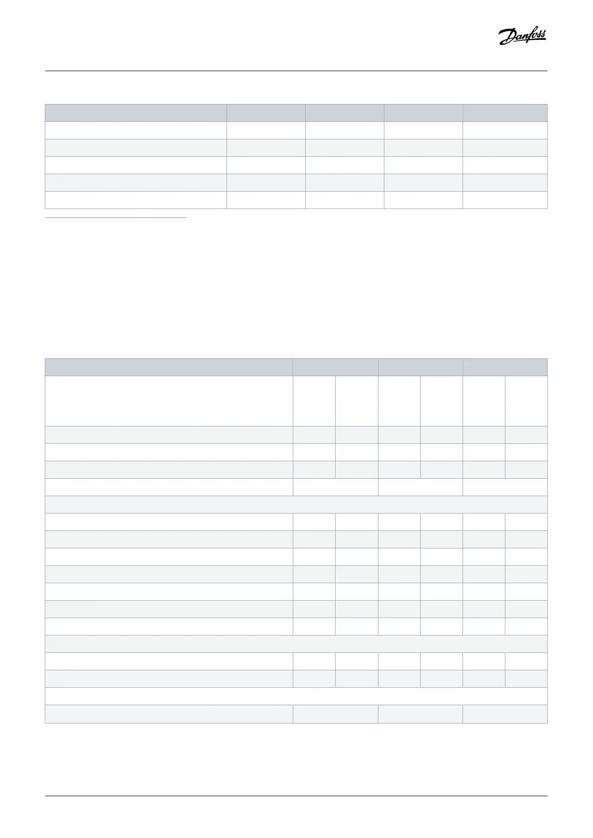
FC 202 N110 N132 N160 N200
Heat sink overtemperature trip [°C (°F)] 110 (230) 110 (230) 110 (230) 110 (230)
Control card overtemperature trip [°C (°F)] 80 (176) 80 (176) 80 (176) 80 (176)
PHF overtemperature trip [°C (°F)] 150 (302) 150 (302) 150 (302) 150 (302)
dU/dt filter overtemperature trip [°C (°F)] 150 (302) 150 (302) 150 (302) 150 (302)
Sine-wave filter overtemperature trip [°C (°F)] 150 (302) 150 (302) 150 (302) 150 (302)
1
Typical power loss is at normal conditions and expected to be within ±15% (tolerance relates to variety in voltage and cable conditions.) These values are based on a typical motor
efficiency (IE/IE3 border line). Lower efficiency motors add to the power loss in the drive. Applies to dimensioning of drive cooling. If the switching frequency is higher than the default
setting, the power losses can increase. LCP and typical control card power consumptions are included. For power loss data according to EN 50598-2, refer to drives.danfoss.com/
knowledge-center/energy-efficiency-directive/#/. Options and customer load can add up to 30 W to the losses, though usually a fully loaded control card and options for slots A and B
each add only 4 W.
2
Measured using 5 m (16.4 ft) shielded motor cables at rated load and rated frequency. Efficiency measured at nominal current. For energy efficiency class, see the Ambient Conditions
section. For part load losses, see drives.danfoss.com/knowledge-center/energy-efficiency-directive/#/.
3
See also Input Power Option Losses.
4
If using an output filter, the output frequency is limited further. See the Motor Output (U, V, W) section.
Table 83: Electrical Data, Mains Supply 3x525–690 V AC
FC 202 N250 N315 N400
High/normal overload
High overload=150% or 160% torque for a duration of 60 s.
Normal overload=110% torque for a duration of 60 s.
HO NO HO NO HO NO
Typical shaft output at 550 V [kW] 160 200 200 250 250 315
Typical shaft output at 575 V [hp] 250 300 300 350 350 400
Typical shaft output at 690 V [kW] 200 250 250 315 315 400
Enclosure size D10h D10h D10h
Output current (3-phase)
Continuous (at 550 V) [A] 395 303 303 360 360 418
Intermittent (60 s overload) (at 550 V) [A] 380 333 455 396 540 460
Continuous (at 575/690 V) [A] 242 290 290 344 344 400
Intermittent (60 s overload) (at 575/690 V) [A] 363 319 435 378 516 440
Continuous kVA (at 550 V) [kVA] 230 276 276 327 327 380
Continuous kVA (at 575 V) [kVA] 241 289 289 343 343 398
Continuous kVA (at 690 V) [kVA] 289 347 347 411 411 478
Maximum input current
Continuous (at 525 V) [A] 381 453 413 504 504 574
Continuous (at 575/690 V) [A] 366 434 395 482 482 549
Maximum number and size of cables per phase
- Mains [mm
2
(AWG)]
2x185 (2x350 mcm) 2x185 (2x350 mcm) 2x185 (2x350 mcm)
Specifications
Operating Guide | VLT® AQUA Drive FC 202
AQ262141056213en-000101 / 130R0882
166 | Danfoss A/S © 2018.10

 Loading...


