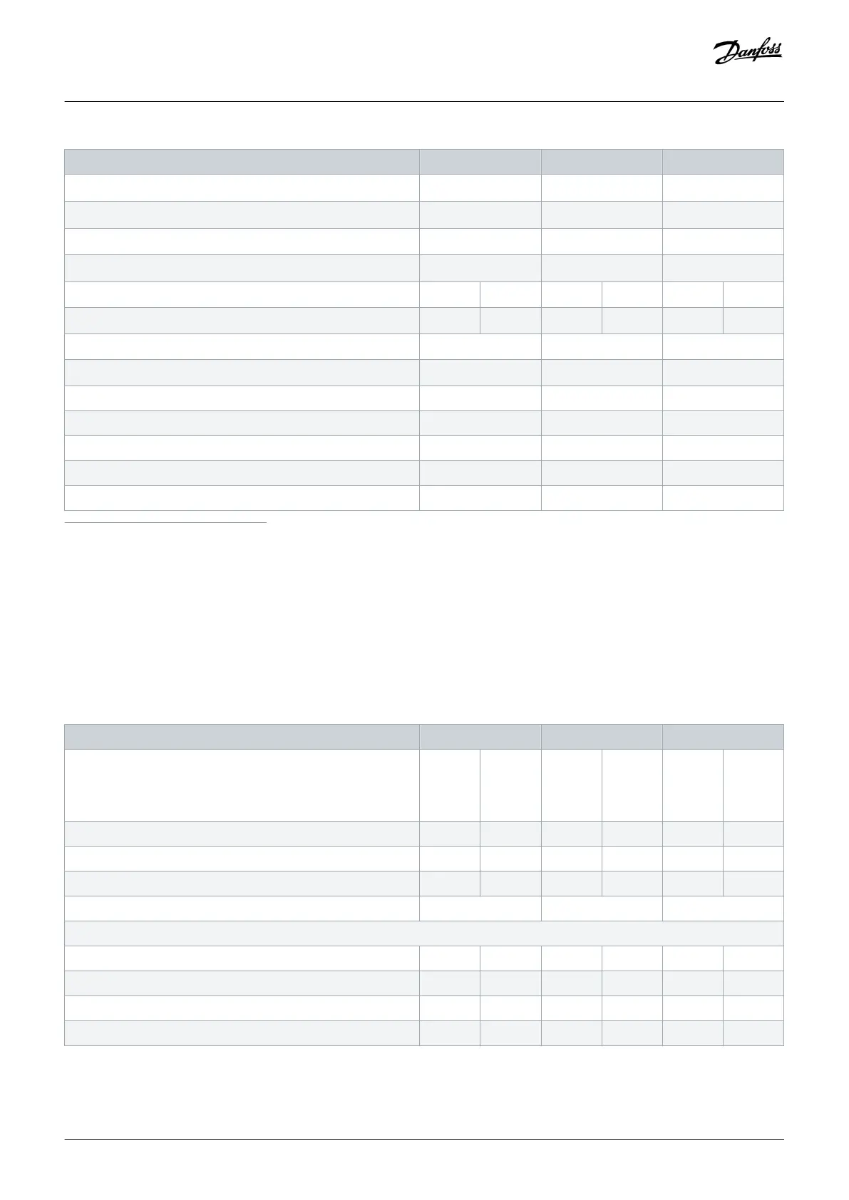
FC 202 N250 N315 N400
- Mains with disconnect [mm
2
(AWG)]
2x185 (2x350 mcm) 2x185 (2x350 mcm) 2x185 (2x350 mcm)
- Mains with fusible disconnect [mm
2
(AWG)]
2x185 (2x350 mcm) 2x185 (2x350 mcm) 2x185 (2x350 mcm)
- Mains with contactor [mm
2
(AWG)]
2x185 (2x350 mcm) 2x185 (2x350 mcm) 2x185 (2x350 mcm)
- Motor [mm
2
(AWG)]
2x185 (2x350 mcm) 2x185 (2x350 mcm) 2x185 (2x350 mcm)
Drive module power loss at 600 V [W]
(1) (2) (3)
3012 3723 3642 4465 4146 5028
Drive module power loss at 690 V [W]
(1) (2) (3)
3123 3851 3771 4614 4258 5155
Drive efficiency
(2)
0.98 0.98 0.98
Output frequency [Hz]
(4)
0–590 0–590 0–590
Heat sink overtemperature trip [°C (°F)] 110 (230) 110 (230) 110 (230)
Control card overtemperature trip [°C (°F)] 80 (176) 80 (176) 80 (176)
PHF overtemperature trip [°C (°F)] 150 (302) 150 (302) 150 (302)
dU/dt filter overtemperature trip [°C (°F)] 150 (302) 150 (302) 150 (302)
Sine-wave filter overtemperature trip [°C (°F)] 150 (302) 150 (302) 150 (302)
1
Typical power loss is at normal conditions and expected to be within ±15% (tolerance relates to variety in voltage and cable conditions.) These values are based on a typical motor
efficiency (IE/IE3 border line). Lower efficiency motors add to the power loss in the drive. Applies to dimensioning of drive cooling. If the switching frequency is higher than the default
setting, the power losses can increase. LCP and typical control card power consumptions are included. For power loss data according to EN 50598-2, refer to drives.danfoss.com/
knowledge-center/energy-efficiency-directive/#/. Options and customer load can add up to 30 W to the losses, though usually a fully loaded control card and options for slots A and B
each add only 4 W.
2
Measured using 5 m (16.4 ft) shielded motor cables at rated load and rated frequency. Efficiency measured at nominal current. For energy efficiency class, see the Ambient Conditions
section. For part load losses, see drives.danfoss.com/knowledge-center/energy-efficiency-directive/#/.
3
See also Input Power Option Losses.
4
If using an output filter, the output frequency is limited further. See the Motor Output (U, V, W) section.
Table 84: Electrical Data, Mains Supply 3x525–690 V AC
FC 202 N450 N500 N560
High/normal overload
High overload=150% or 160% torque for a duration of 60 s.
Normal overload=110% torque for a duration of 60 s.
HO NO HO NO HO NO
Typical shaft output at 550 V [kW] 315 355 315 400 400 450
Typical shaft output at 575 V [hp] 400 450 400 500 500 600
Typical shaft output at 690 V [kW] 355 450 400 500 500 560
Enclosure size E5h E5h E5h
Output current (3-phase)
Continuous (at 550 V) [A] 395 470 429 523 523 596
Intermittent (60 s overload) (at 550 V) [A] 593 517 644 575 785 656
Continuous (at 575/690 V) [A] 380 450 410 500 500 570
Intermittent (60 s overload) (at 575/690 V) [A] 570 495 615 550 750 627
Specifications
Operating Guide | VLT® AQUA Drive FC 202
AQ262141056213en-000101 / 130R0882 | 167
Danfoss A/S © 2018.10

 Loading...


