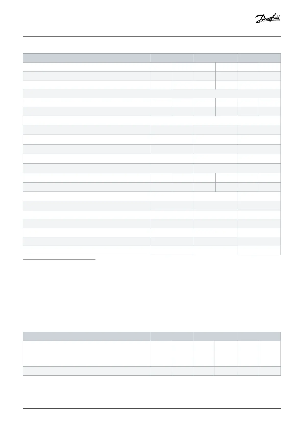
FC 202 N450 N500 N560
Continuous kVA (at 550 V) [kVA] 376 448 409 498 498 568
Continuous kVA (at 575 V) [kVA] 378 448 408 498 498 568
Continuous kVA (at 690 V) [kVA] 454 538 490 598 598 681
Maximum input current
Continuous (at 525 V) [A] 381 453 413 504 504 574
Continuous (at 575/690 V) [A] 366 434 395 482 482 549
Maximum number and size of cables per phase
- Mains [mm
2
(AWG)]
4x120 (4x250 mcm) 4x120 (4x250 mcm) 4x120 (4x250 mcm)
- Mains with disconnect [mm
2
(AWG)]
4x120 (4x250) 4x120 (4x250) 4x120 (4x250)
- Mains with fusible disconnect [mm
2
(AWG)]
4x120 (4x250) 4x120 (4x250) 4x120 (4x250)
- Mains with contactor [mm
2
(AWG)]
4x120 (4x250) 4x120 (4x250) 4x120 (4x250)
- Motor [mm
2
(AWG)]
4x120 (4x250) 4x120 (4x250) 4x120 (4x250)
Drive module power loss at 600 V [W]
(1) (2) (3)
4989 6062 5419 6879 6833 8076
Drive module power loss at 690 V [W]
(1) (2) (3)
4920 5939 5332 6715 6678 7852
Drive efficiency
(2)
0.98 0.98 0.98
Output frequency [Hz]
(4)
0–590 0–590 0–590
Heat sink overtemperature trip [°C (°F)] 110 (230) 110 (230) 110 (230)
Control card overtemperature trip [°C (°F)] 80 (176) 80 (176) 80 (176)
PHF overtemperature trip [°C (°F)] 150 (302) 150 (302) 150 (302)
dU/dt filter overtemperature trip [°C (°F)] 150 (302) 150 (302) 150 (302)
Sine-wave filter overtemperature trip [°C (°F)] 150 (302) 150 (302) 150 (302)
1
Typical power loss is at normal conditions and expected to be within ±15% (tolerance relates to variety in voltage and cable conditions.) These values are based on a typical motor
efficiency (IE/IE3 border line). Lower efficiency motors add to the power loss in the drive. Applies to dimensioning of drive cooling. If the switching frequency is higher than the default
setting, the power losses can increase. LCP and typical control card power consumptions are included. For power loss data according to EN 50598-2, refer to drives.danfoss.com/
knowledge-center/energy-efficiency-directive/#/. Options and customer load can add up to 30 W to the losses, though usually a fully loaded control card and options for slots A and B
each add only 4 W.
2
Measured using 5 m (16.4 ft) shielded motor cables at rated load and rated frequency. Efficiency measured at nominal current. For energy efficiency class, see the Ambient Conditions
section. For part load losses, see drives.danfoss.com/knowledge-center/energy-efficiency-directive/#/.
3
See also Input Power Option Losses.
4
If using an output filter, the output frequency is limited further. See the Motor Output (U, V, W) section.
Table 85: Electrical Data, Mains Supply 3x525–690 V AC
FC 202 N630 N710 N800
High/normal overload
High overload=150% or 160% torque for a duration of 60 s.
Normal overload=110% torque for a duration of 60 s.
HO NO HO NO HO NO
Typical shaft output at 550 V [kW] 450 500 500 560 560 670
Specifications
Operating Guide | VLT® AQUA Drive FC 202
AQ262141056213en-000101 / 130R0882
168 | Danfoss A/S © 2018.10

 Loading...


