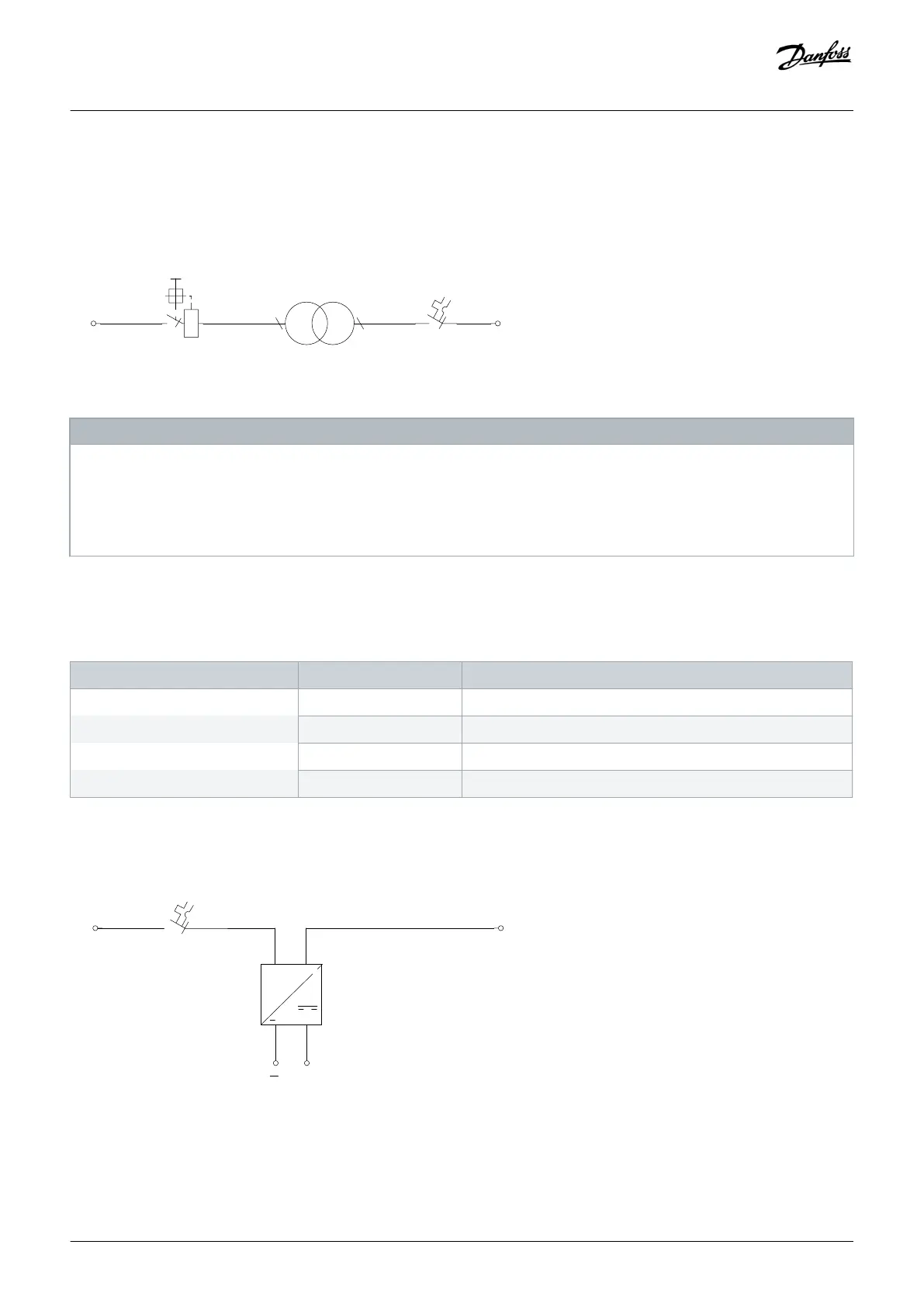
The transformer has multiple tappings on the primary side for the standard range of voltages on which the drive operates. The factory
default wiring connects to the highest voltage tapping on the primary side, and the trip settings for the -FC4 terminal is set
accordingly. The customer can change the tapping provided the correct voltage is applied and the thermal magnetic circuit breaker is
set accordingly.
Illustration 43: Auxiliary Voltage Transformer Terminals
NOTI C E
AUXILIARY COMPONENT FAILURE
Incorrect voltage or incorrect tapping installation will cause other auxiliary components in the control compartment to fail.
-
When tapping the transformer, make sure to apply the correct voltage for the drive.
-
Use the correct tapping and trip settings.
5.7.6.3 +24 DC External Supply
Table 35: Auxiliary Supply Codes
Character position Option code Description
21 4 230 V AC internal+24 V DC internal
5 230 V AC external+24 V DC internal
8 120 V AC internal+24 V DC internal
9 120 V AC external+24 V DC internal
The 24 V DC external supply option enables other auxiliary options to be connected to a 24 V DC supply within the control
compartment.
Illustration 44: 24 V DC External Supply Terminals
Electrical Installation
Operating Guide | VLT® AQUA Drive FC 202
AQ262141056213en-000101 / 130R0882 | 73
Danfoss A/S © 2018.10

 Loading...


