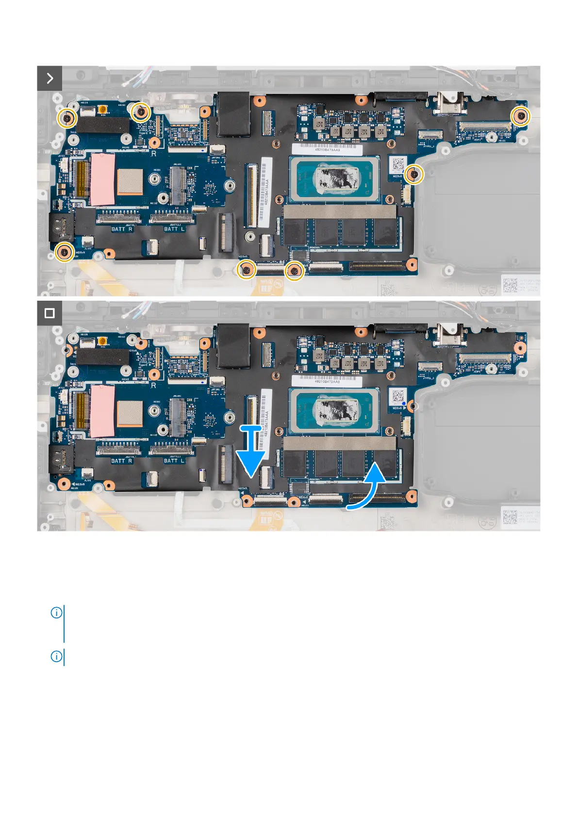
Figure 92. Removing the system board
Steps
1. Remove the two epoxy cap screws that secure the serial RS-232 port to the computer chassis and then remove the serial
RS-232 port from the computer chassis.
NOTE:
The epoxy screw locations require additional focus. These screws are difficult to remove, and damage might
occur during the removal process. To prevent damage to the screws and surrounding plastics, please use the correct
screwdriver for each screw type.
NOTE: To remove the epoxy cap screws, use a 5.5 mm hex socket wrench.
2. Disconnect the touchpad flat printed cable from its connector on the system board.
3. Disconnect the following cables from their connector on the system board : power button board, RF switch board, Dock I/O
flat printed cable, EDP cable, Left I/O board flat printed cable connector, express card reader board connector, USH board
connector, smart card reader connector, and LED board connector.
4. Remove the seven (M2.5x5) screws that secure the system board to the computer chassis and lift the system board.
Removing and installing Field Replaceable Units (FRUs)
131