Installing the system board
CAUTION: The information in this installation section is intended for authorized service technicians only.
Prerequisites
If you are replacing a component, remove the existing component before performing the installation procedure.
About this task
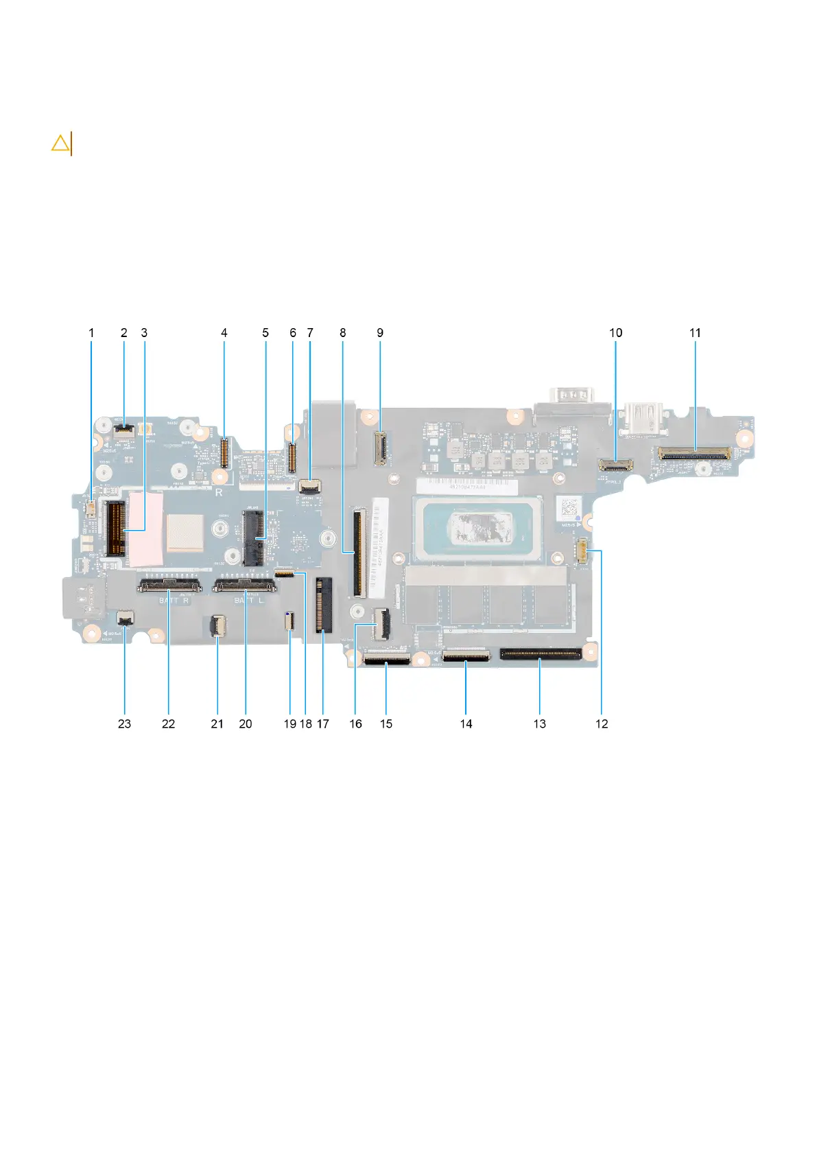
The following image indicates the connectors on your system board.
Figure 93. System board connectors
1. Coin-cell battery connector
2. Power-button board cable connector
3. WWAN card connector
4. Right Type-C cable connector
5. WLAN card connector
6. Left Type-C cable connector
7. RF switch board connector
8. Dock I/O flat printed cable connector
9. Right Type-C flat printed cable connector
10. Left Type-C flat printed cable connector
11. eDP cable connector
12. Fan cable connector
13. Left I/O-board flat printed cable connector
132
Removing and installing Field Replaceable Units (FRUs)