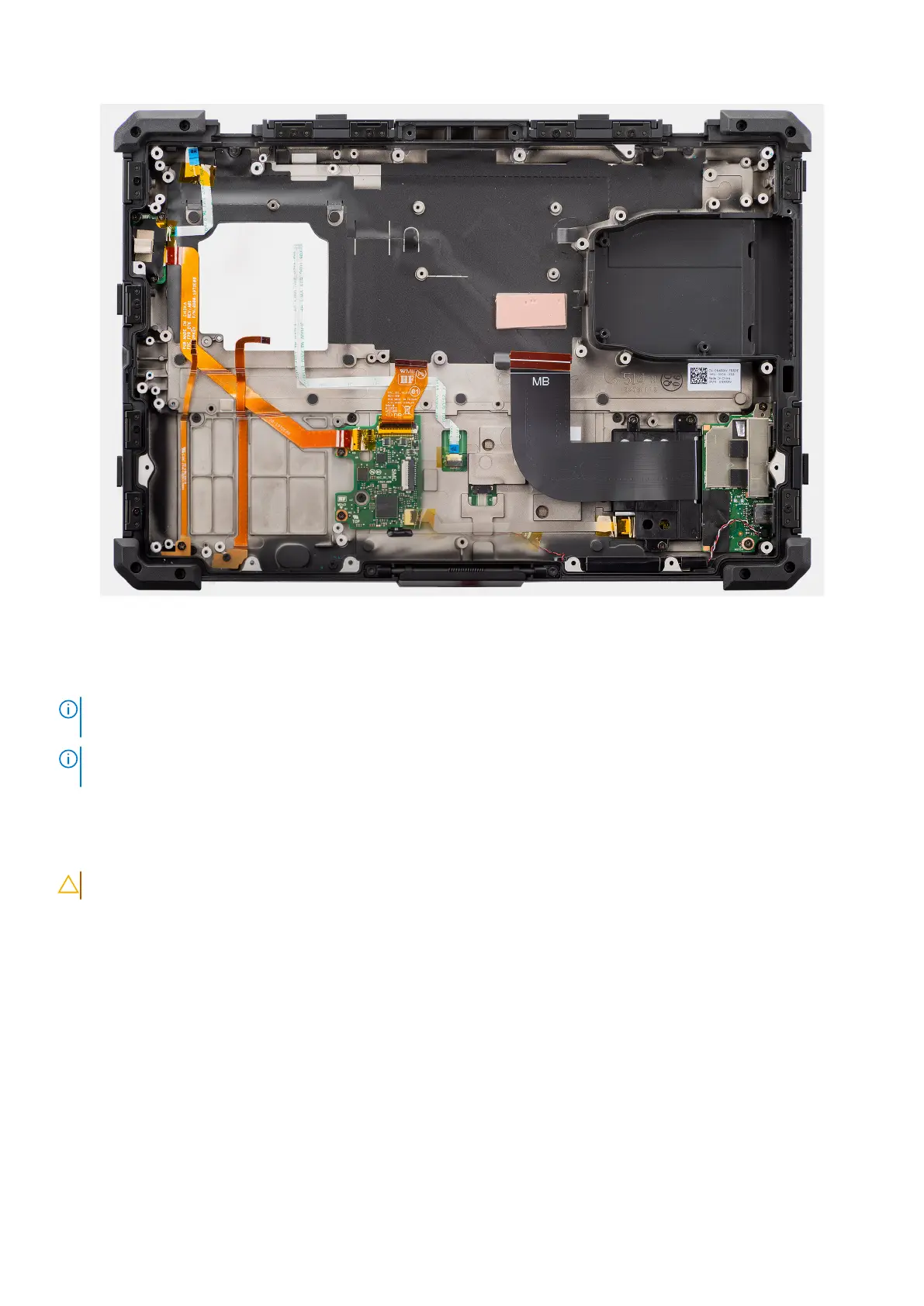
Figure 122. Removing the palm-rest assembly
Steps
After performing the preceding steps, you are left with the palm-rest assembly.
NOTE:
The palm-rest assembly is preassembled with the touchpad, power button board, power button with fingerprint
reader, LED board, USH board, left I/O-board, speakers, NFC module.
NOTE: Depending on the configuration of the computer, the rear I/O-board (including cover) and optional Fischer port
must be transferred over to the new replacement palm-rest assembly.
Installing the palm-rest assembly
CAUTION: The information in this installation section is intended for authorized service technicians only.
Prerequisites
If you are replacing a component, remove the existing component before performing the installation procedure.
About this task
The following image indicates the location of the palm-rest assembly and provides a visual representation of the installation
procedure.
Removing and installing Field Replaceable Units (FRUs)
161