80
Press the key , to get to the next diagnosis page or , to go the previous diagnosis
page.
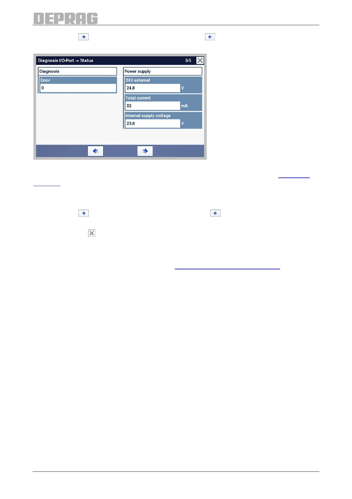
Figure 70: Diagnosis I/O-Port, Status (Page 5)
The "Errors" field contains the error number of the last I/O interface error (see 15.1.5 I/O
interface).
The 24 V DC feed at interface SPS1 (GX2) is displayed in the field "24 V external". The
total current represents the load on all the exits of interface SPS1 (GX2) and SPS2 (GX3).
Press the key , to get to the next diagnostics page or , to go the previous diagnostics
page.
Press on the key , to exit the diagnostics of the I/O interface.
9.2.7.4 Fieldbus (optional)
All the inputs and outputs as well as the communication flags of the fieldbus interface can
be examined in the Fieldbus menu (also see 6.2.8 Fieldbus interface (optional)).
The fieldbus menu can be opened only if a fieldbus module has been installed.
Testing the inputs:
After applying a signal at one input, the indication for the corresponding input lights up.
Inputs at which there is a signal are shown in yellow (see “Ready” in the following figure),
all other inputs are shown in grey.
Testing the outputs:
The outputs can be activated by means of the switches to the left beside the name. By
tapping the switch several times, the respective output is switched off again.
The switches for the outputs where there is a signal are shown in yellow, all the other
switches are shown in grey.