83
All the outputs for Profibus / Profinet are described in section 7.6.1.3.3 Description of the
data structure of the status signals (UDT22) and for EtherNet/IP in section 7.6.2.4.2
Description - data structure AST40_IN_Signals.
Designation
AST40 Profibus / Profinet EtherNet/IP
System OK (HS + LT) SystemOk SYSTEM_OK
ready Ready READY
Screwdriving cycle active CycleActive Cycle_active
OK Ok OK
NOK Nok NOK
Emergency stop 1 active Sto1active Sto1_active
Emergency stop 2 active Sto2active Sto2_active
Sequence 1 ProgOut1 OUT_ScrPrg_1
Sequence 2 ProgOut2 OUT_ScrPrg_2
Sequence 3 ProgOut3 OUT_ScrPrg_3
Sequence 4 ProgOut4 OUT_ScrPrg_4
Reload Reload Reload
Table 29: Diagnosis Fieldbus, Outputs (Page 4)
Press the key , to get to the next diagnostics page or , to go the previous diagnosis
page.
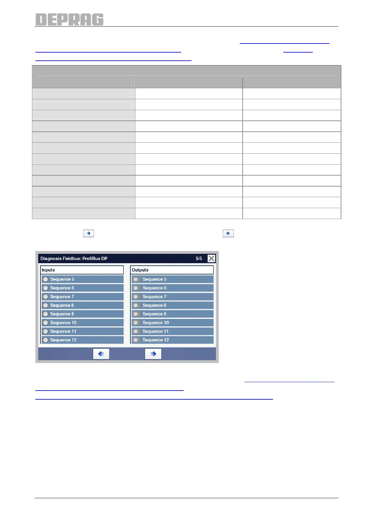
Figure 75: Diagnosis Fieldbus, Universal Inputs and Outputs (Page 5)
Using Profibus / Profinet all the inputs are described in section 7.6.1.3.2 Description of the
data structure of the control signals (UDT21), all the outputs are described in section
7.6.1.3.3 Description of the data structure of the status signals (UDT22).