84
Using EtherNet / IP all the inputs are described in section 7.6.2.4.2 Description - data
structure AST40_IN_Signals, all the outputs are described in section 7.6.2.4.4 Description
- data structure AST40_OUT_Signals.
Designation
AST40 Profibus / Profinet EtherNet/IP
Sequence 5 ProgIn5 IN_Signals.uni_IO.0
Sequence 6 ProgIn6 IN_Signals.uni_IO.1
Sequence 7 ProgIn7 IN_Signals.uni_IO.2
Sequence 8 ProgIn8 IN_Signals.uni_IO.3
Sequence 9 ProgIn9 IN_Signals.uni_IO.4
Sequence 10 ProgIn10 IN_Signals.uni_IO.5
Sequence 11 ProgIn11 IN_Signals.uni_IO.6
Sequence 12 ProgIn12 IN_Signals.uni_IO.7
Sequence 5 ProgOut5 OUT_Signals.uni_IO.0
Sequence 6 ProgOut6 OUT_Signals.uni_IO.1
Sequence 7 ProgOut7 OUT_Signals.uni_IO.2
Sequence 8 ProgOut8 OUT_Signals.uni_IO.3
Sequence 9 ProgOut9 OUT_Signals.uni_IO.4
Sequence 10 ProgOut10 OUT_Signals.uni_IO.5
Sequence 11 ProgOut11 OUT_Signals.uni_IO.6
Sequence 12 ProgOut12 OUT_Signals.uni_IO.7
Table 30: Diagnosis Fieldbus, Universal Inputs and Outputs (Page 5)
Press the key , to get to the next diagnostics page or , to go the previous diagnostics
page.
Press on , to exit Fieldbus Diagnostics.
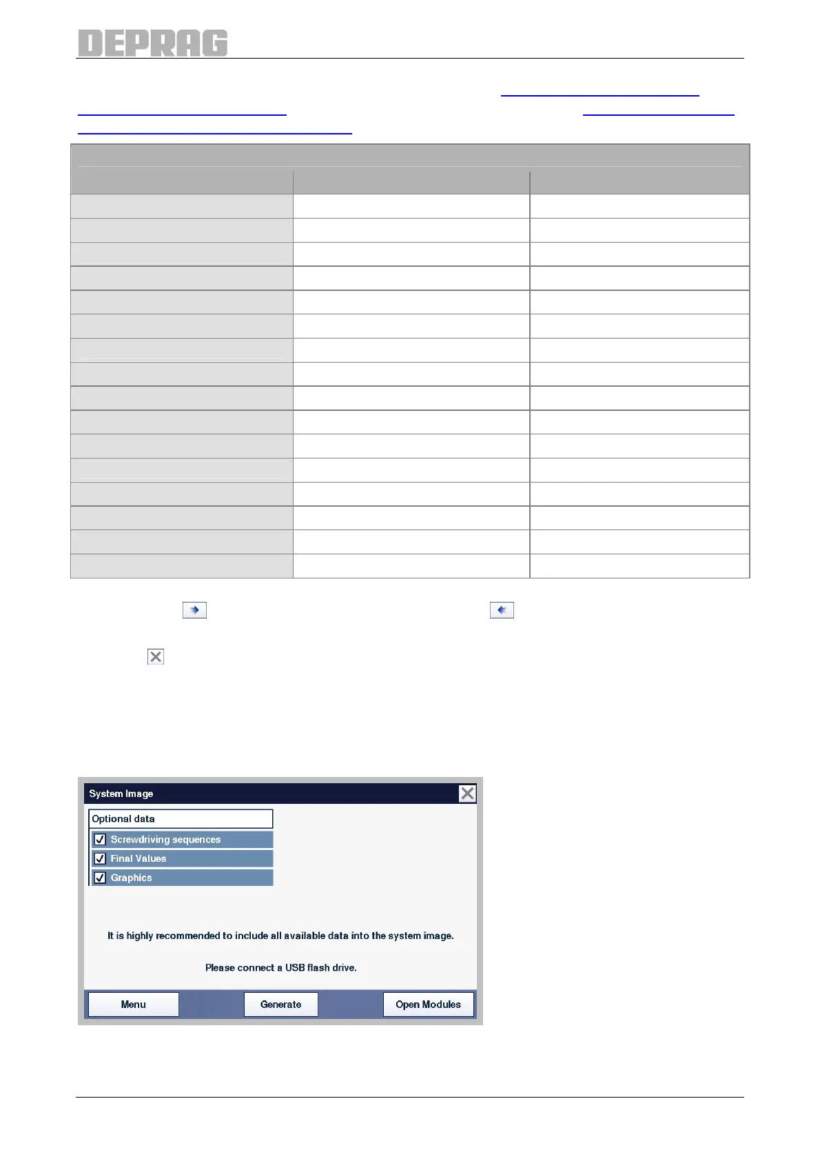
9.2.7.5 System Image
The System Image menu can produce a complete system map of the AST40.
The system image can help to quickly and safely diagnose an AST40 error in the event of
an error.
Figure 76: System Image
The system image contains fundamental information about the AST40 system.

 Loading...
