77
Testing the inputs:
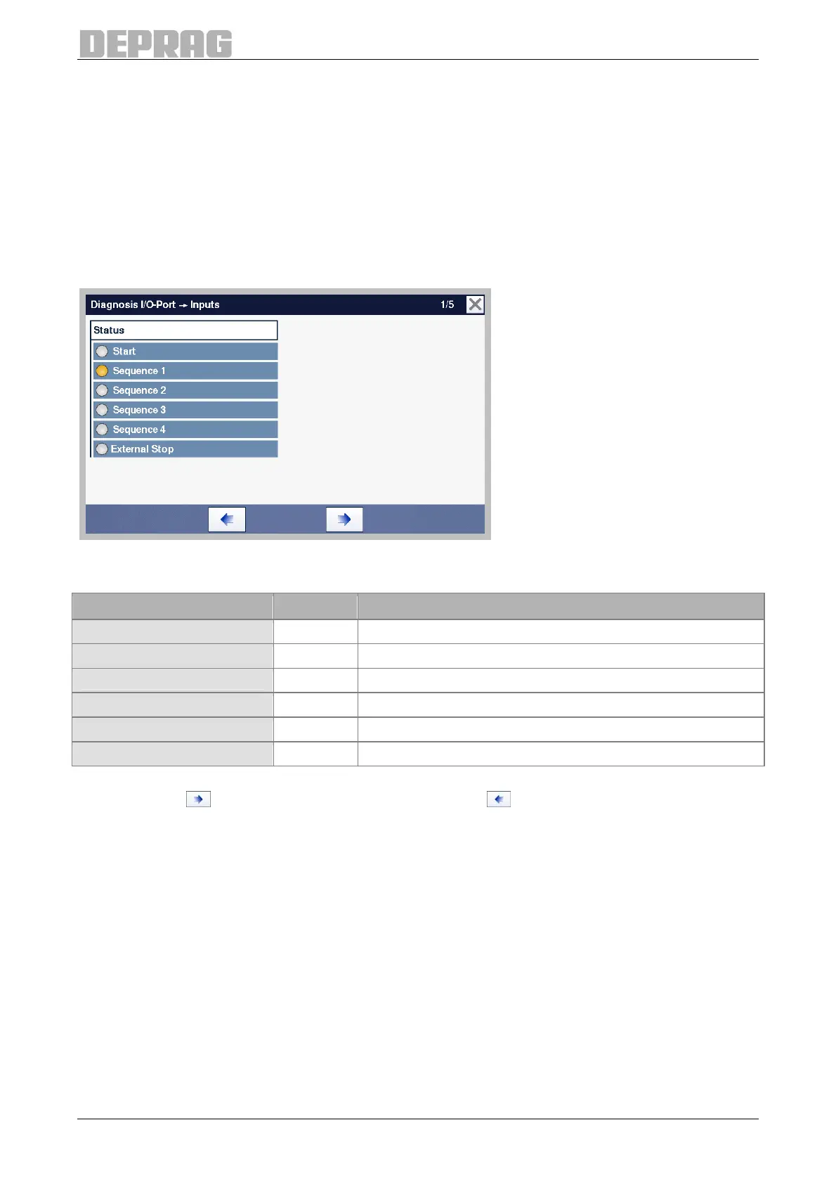
After applying a signal at one input, the indication for the corresponding input lights up.
Inputs at which there is a signal are shown in yellow (see “Screwdriving program 1” in the
following figure), all other inputs are shown in grey.
Testing the outputs:
The outputs can be activated by means of the switches to the left beside the name. By
tapping the switch several times, the respective output is switched off again.
The switches for the outputs where there is a signal are shown in yellow, all the other
switches are shown in grey.
Figure 66: Diagnosis I/O-Port, Inputs (Page 1)
All the inputs are located on the SPS1 (GX2) interface.
Designation Pin Description
Start 27 Start signal for the EC-servo screwdriver
Sequence 1 32 Input 1 in the command "Wait for input“
Sequence 2 33 Input 2 in the command "Wait for input“
Sequence 3 34 Input 3 in the command "Wait for input“
Sequence 4 5 Input 4 in the command "Wait for input“
external stop, digital 8 Used in command "Fasten to external stop signal“
Table 23: Diagnosis I/O-Port, Inputs (Page 1)
Press the key , to get to the next diagnosis page or , to go the previous diagnosis
page.

 Loading...
