81
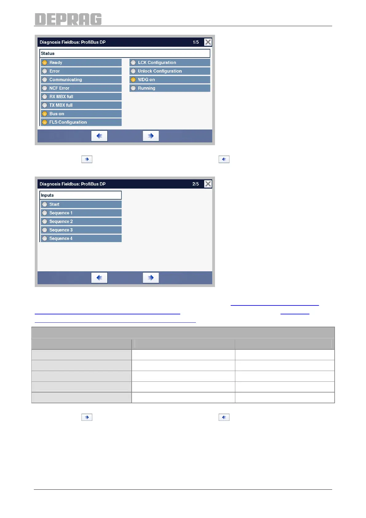
Figure 71: Diagnosis Fieldbus, Communication Flags (Page 1)
Press the key , to get to the next diagnostics page or , to go the previous diagnosis
page.
Figure 72: Diagnosis Fieldbus, Inputs (Page 2)
All the inputs for Profibus / Profinet are described in section 7.6.1.3.2 Description of the
data structure of the control signals (UDT21)
and for EtherNet/IP in section 7.6.2.4.4
Description - data structure AST40_OUT_Signals
.
Designation
AST40 Profibus / Profinet EtherNet/IP
Start Start START
Sequence 1 ProgIn1 ScrPRG_1
Sequence 2 ProgIn2 ScrPRG_2
Sequence 3 ProgIn3 ScrPRG_3
Sequence 4 ProgIn4 ScrPRG_4
Table 27: Fieldbus, Inputs Diagnosis (Page 2)
Press the key , to get to the next diagnostics page or , to go the previous diagnosis
page.

 Loading...
