Manuale operativo
CHORUS
Rev. 0 del 06/2012 11
1.3.1 F
RONT SIDE
1.3.1.1 Introduction of the strips
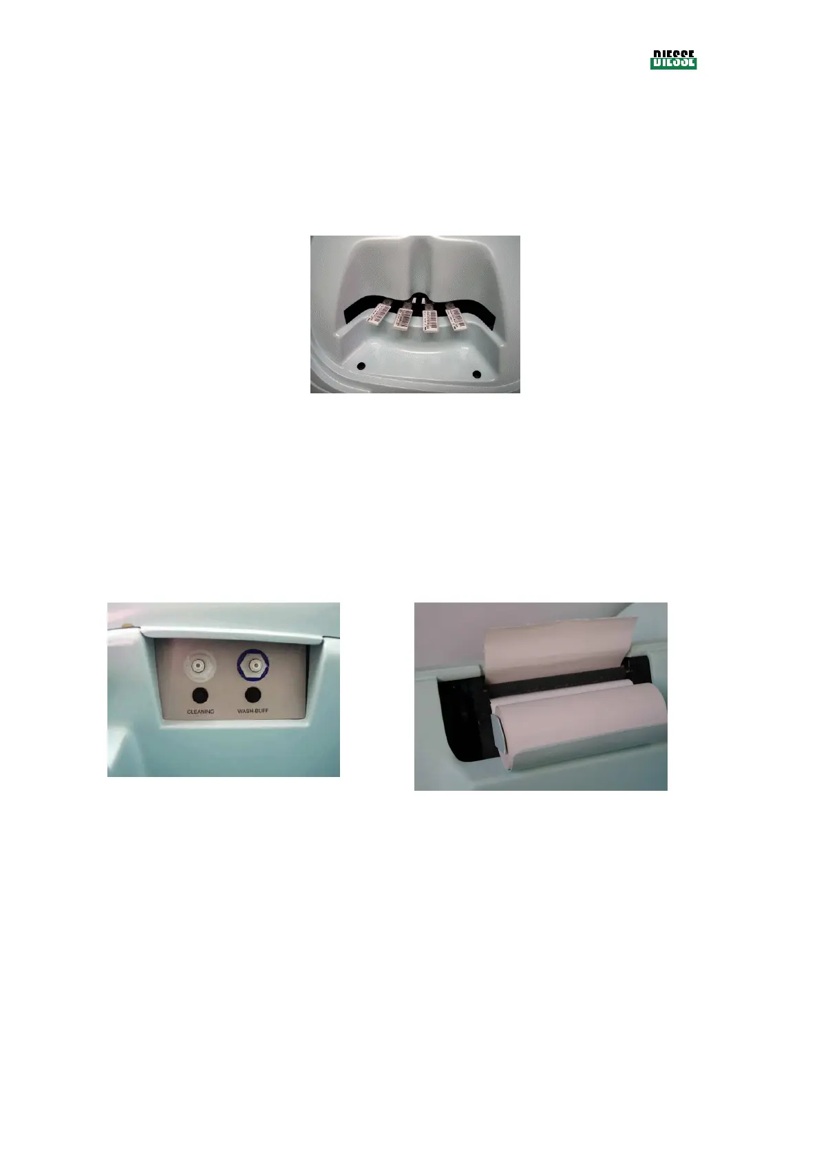
By lifting the cover with the green port-hole positioned on the left front side of the instrument (A) fig. 1,
it is possible to access the zone to insert strips into the tray (see fig. 2).
fig. 2
Each position of the carousel has a number and up to 30 strips can be inserted for each testing
session.
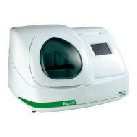
1.3.1.2 Liquid tanks and printer
The opening on the right side of the top of the instrument (B) in fig. 1, provides access to the internal
space where the tanks and hydraulic and electric connectors to the level sensors of each tank are
planned (see fig. 3).
The same opening reaches the area that contains the roll of thermal paper and the lever for the printing
mechanism (see fig. 4).
1.3.1.3 Display
On the right side of the instrument there is a touch-screen color display. The display is used as a video
and as a keyboard.