Manuale operativo
CHORUS
26 Rev. 0 del 06/2012
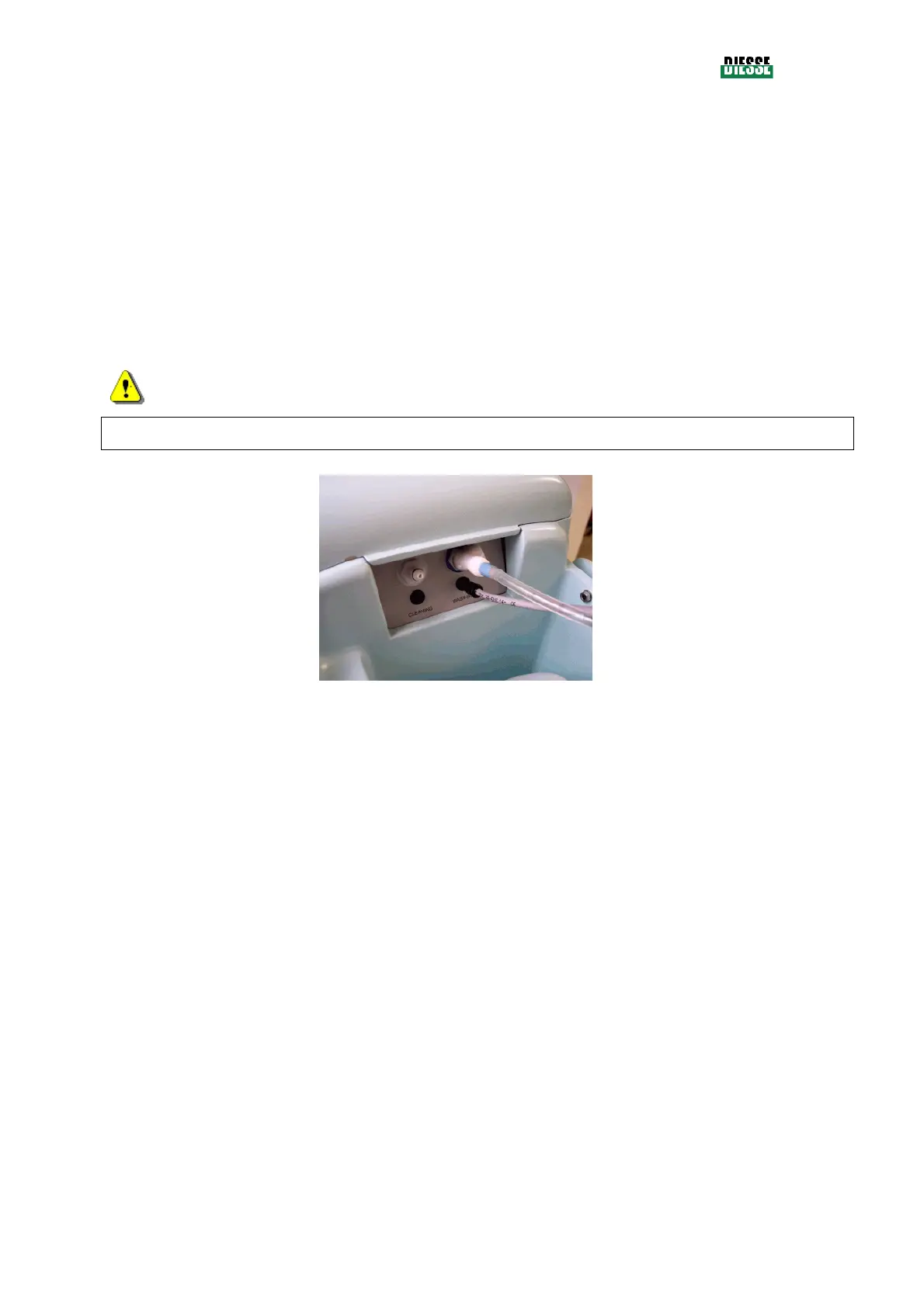
Each of the probes that must be inserted into the tanks (see fig. 17), is equipped with two terminals:
- a plastic tube with relative connector, for aspiration of the liquid, identified by a blue
(Infectious Washing buffer), green (Autoimmunity Washing buffer) or white band (Cleaning
solution),
- an electric cable with relative connector, for detection of the level of the liquid which must
be connected to the respective plugs as shown in fig 19).
Use the probe with the blue band for the tank of the Infectious Washing Buffer, the one with
the green band for the tank of the Autoimmunity Washing Buffer and the one with the white
band for the Cleaning Solution, following the coloring around the entrance on the
instrument.
ATTENTION
Each probe must always be used for the same solution to avoid cross-contamination.
fig. 18
3.2.2.1 Washing buffers
The instrument uses two types of washing buffers collected in a tank of 1lt.
The buffer for the infectious diseases tests has code 42461 and is identified by the blue color.
The buffer for the autoimmunity tests has the code 42462 and is identified by the green color.
The buffer solutions are prepared, following the written instructions, in the respective user manual, in
an appropriate container and then poured into the tanks used, that have to be positioned in the
appropriate compartment in the instrument.
After this the tank that one wants to use has to be chosen, positioned in the compartment of the
instrument and the catching probe introduced into the Washing Buffer.
3.2.2.2 Cleaning Solution
The instrument uses a Cleaning Solution collected in a 2lt tank.
The solution is collected in a tank with code 43531 and is identified by the color white.
The cleaning solution is prepared following the instructions written in the user manual, and then poured
into the tank that has to be positioned in the appropriate compartment in the instrument.
In it the catching and level detection probe is positioned that has to be attached to the instrument
according to the following rule
- place the tank in the compartment