Manuale operativo
CHORUS
Rev. 0 del 06/2012 29
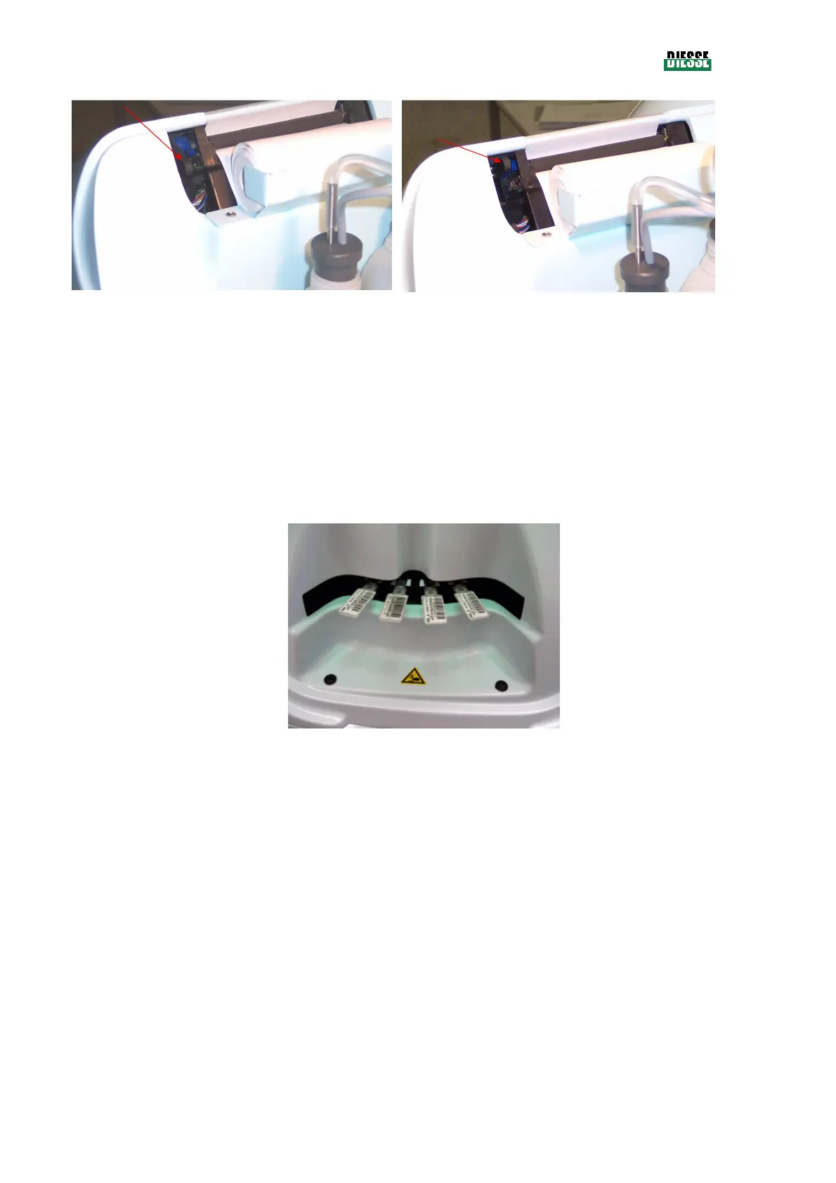
fig. 20
fig. 21
3.2.5 S
TRIP INTRODUCTION
This operation is not strictly connected to switching on the instrument, except for the fact that during
the phase of the initial automatic check (chap. 3.4), the operator is asked to insert a strip. When the
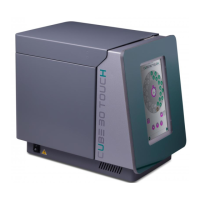
front cover is opened, the inside appears as shown in fig. 22.
The slot where the strip should be inserted is indicated by a hollow in the carter. Each position on the
plate is numbered, and during the guided insertion of the strips, the relative number is shown on the
display.
fig. 22
Insert the strips slowly but firmly until able to feel the spring resistance; then push as far as it will go.
To extract the strips, pull hard until the strip is released from the spring which holds it.
Be careful not to spill the serum.
3.2.6 E
LECTRICAL CONNECTIONS
The power supply is located on the back left hand side of the instrument.
Use only the cable supplied with the instrument for connection to the power supply, without using
reducers or extensions which could reduce the protection incorporated in the system against electric
shocks.
The cable is first connected to the instrument and then, after checking that it is switched off, the other
end of the cable is connected to the power supply.