Manuale operativo
CHORUS
12 Rev. 0 del 06/2012
1.3.2 B
ACK SIDE
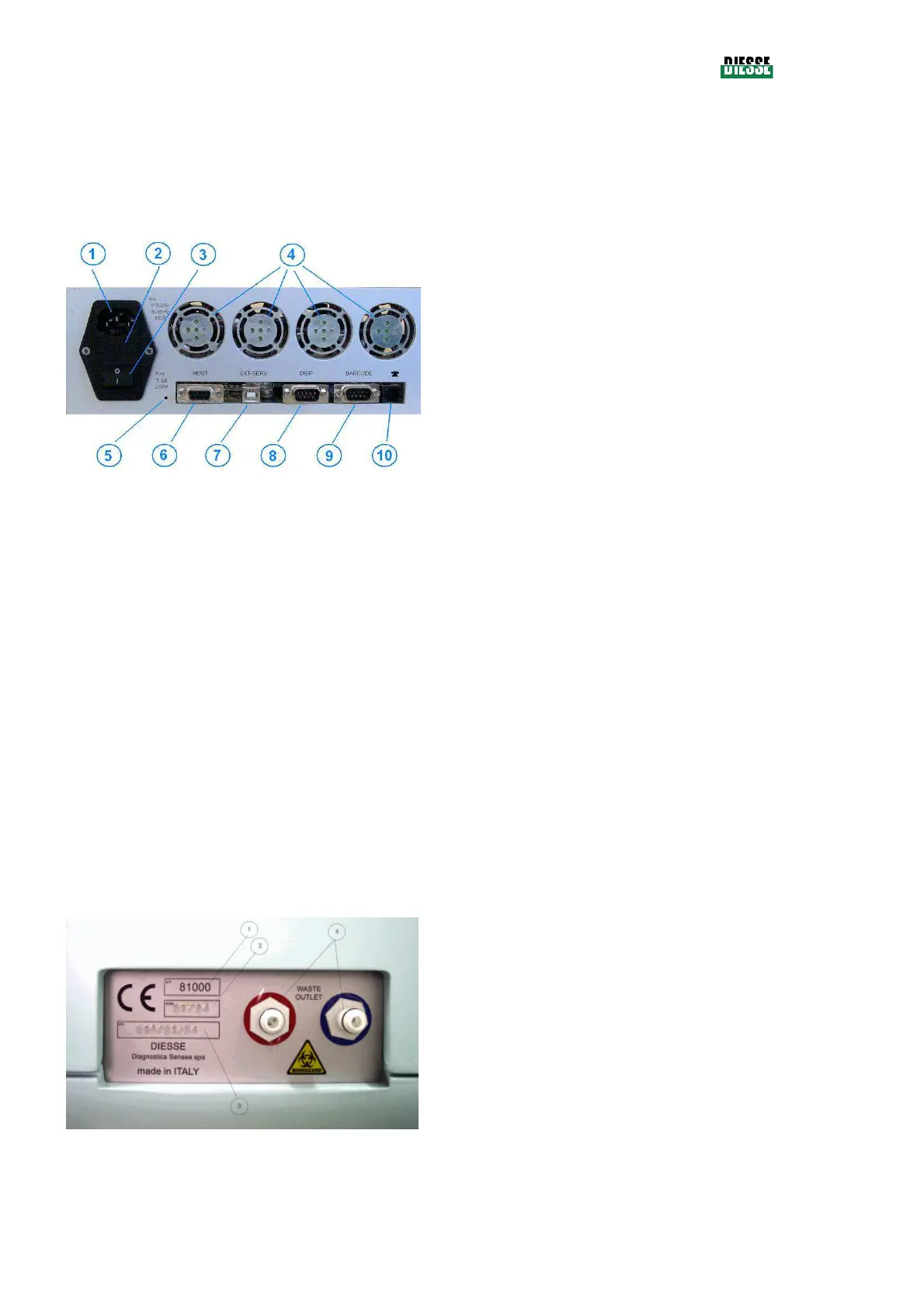
1.3.2.1 Electrical connections
On the back of the instrument on the left the electrical section area is located as described in figure 5.
1. power plug
2. protection fuses
3. on-off switch
4. cooling fan
5. switch for initial programming
6. serial port for connection to the Host
computer
7. USB port for connection to PC for
tecnhical assistance
8. serial port for connection to an external
dispensation system
9. serial connection to external bar code
reader
10. phone connector for remote connection
through modem
fig. 5
The following information is reported next to the power plug:
• Nominal power tension and frequency.
• Maximum consumption.
• Values of the two protection fuses.
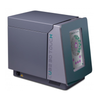
1.3.2.2 Hydraulic connections
The hydraulic section area is located on the back of the instrument on the right side as described in
figure 6.
1. identification code of the CHORUS
product
2. manufacturing date
3. serial number of the instrument
4. bayonet joints for the connections to the
waste tank