44 Installing the enclosures
4004 Series 2U controller enclosures cabled to supported drive enclosures
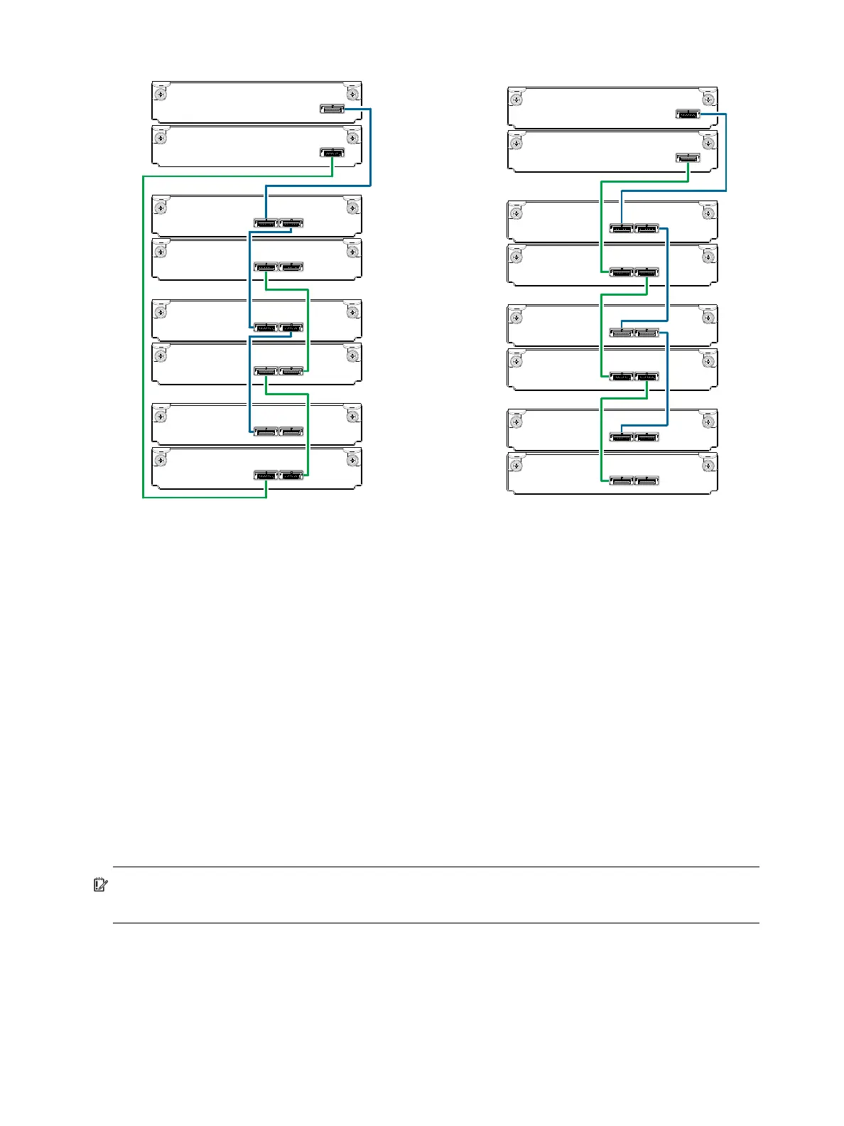
Figure 38 Fault-tolerant cabling between a dual-IOM 2U enclosure and three 2U drive enclosures
The diagram at left (above) shows reverse cabling of a 4004 Series dual-controller 2U enclosure and 2U
drive enclosures configured with dual-expansion modules. Controller module 0A is connected to expansion
module 1A, with a chain of connections cascading down (blue). Controller module 0B is connected to the
lower expansion module (3B), of the last expansion enclosure, with connections moving in the opposite
direction (green). Reverse cabling allows any expansion enclosure to fail—or be removed—while
maintaining access to other enclosures.
The diagram at right (above) shows the same storage components connected using straight-through
cabling. Using this method, if an expansion enclosure fails, the enclosures that follow the failed enclosure
in the chain are no longer accessible until the failed enclosure is repaired or replaced.
The 2U drive enclosures shown in Figure 38 can either be of the same type (all J6G48s, all J6G24s, or all
J6G12s) or they can be a mixture of these models. Given that supported drive enclosure models use 6 Gb
SAS link-rate and SAS2.0 expanders, they can be ordered in desired sequence within the array, following
the controller enclosure.
Refer to these diagrams when cabling multiple compatible drive enclosures together with the 4004 Series
controller enclosure.
IMPORTANT: Guidelines for stacking enclosures in the rack are provided in the rackmount bracket kit
installation sheet provided with your product.
Controller A
Controller B
In
Out
In Out
In Out
In Out
In Out
0A
0B
1A
1B
2A
2B
3A
3B
Controller
enclosure
0
Drive
enclosure
1
Drive
enclosure
2
Drive
enclosure
3
0A
0B
1A
1B
2A
2B
3A
3B
Controller A
Controller B
In
Out
In Out
In Out
In Out
In Out
In
Reverse cabling Straight-through cabling
Out
In Out