SHANGHAI ESURVEY GNSS CO., LTD.
101
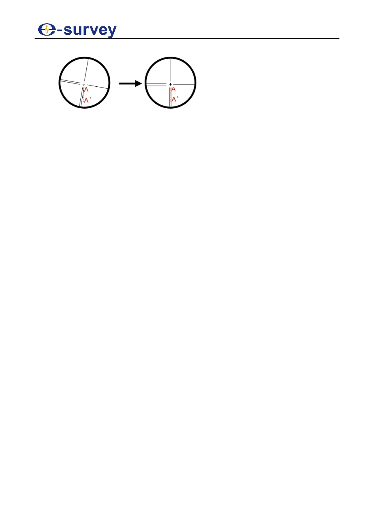
6. Turn the eyepiece end until the vertical line of the reticle overlaps with point A:
7. Tighten the four screws fixing the reticle.
8. Repeat calibration until point A always moves along the vertical line of the reticle.
After doing correction for the vertical line of the telescope reticle, check the collimation
error and index error of the instrument.
See 5.6.1 Horizontal Collimation and 5.6.2 Vertical Index for details.
7.7 Collimation Error of the Instrument
See 5.6.1 Horizontal Collimation for details.
7.8 Index Error of the Vertical Circle
See 5.6.2 Vertical Index for details.
7.9 Zero Position Error of the Tilt Offset
See 5.6.4 Tilt Offset for details.
7.10 Optical Axis and Telescope Sighting Axis for Distance Measurement
It is used to check optical axes of the rangefinder and theodolite for consistency.
Before doing checking and correction for the optical axis and telescope sighting axis for
distance measurement, make sure correction of the eyepiece reticle has been done.
To do checking and correction for the optical axis and telescope sighting axis for distance
measurement, do the following:
1. Place the instrument on a stable device or a tripod, precisely level it and turn it on.
2. Attach the reflector plate supplied along at 5 m ~ 20 m away from the instrument.
3. Collimate the reflector plate, and align the reticle with that on the reflector plate.
4. Set the instrument to the signal test mode.
5. Observe if the laser point hits on the reticle:
o If it does, no correction is required.
o If not, contact us.

 Loading...