Setup & Operation 3. Installation
28 RC620 Rev.8
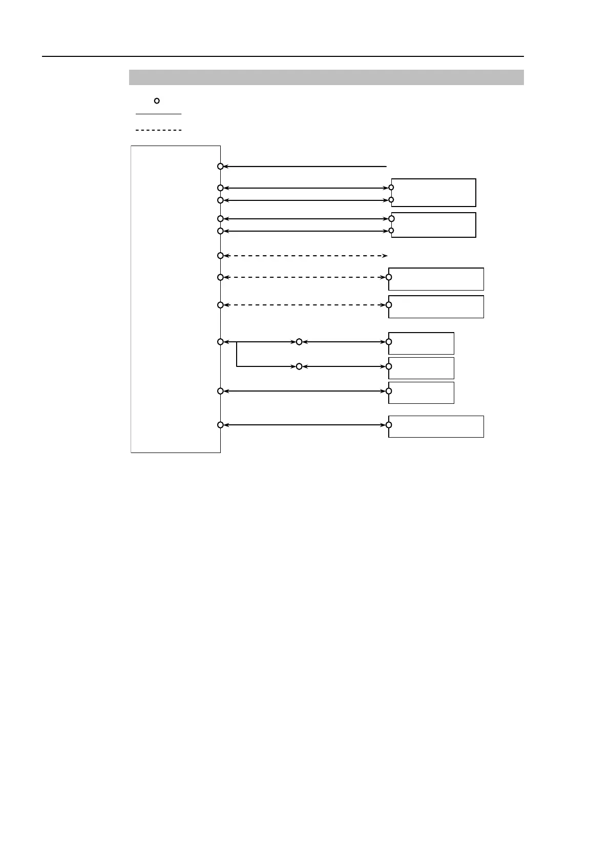
3.4.1 Typical Cable Connection
Emergency Stop
Safety Door, etc.
Disconnectable connector
Cable attached at delivery
Cable prepared by users
Cable for AC 200V power input to the Controller.
Connect the motor power signals between the Manipulator and Controller. Insert
the connectors on the Controller until you hear a “click”.
Connect the encoder signals between the Manipulator and the Controller.
Secure this cable to the Controller for sure using the set screws on both sides of the
Controller.
The EMERGENCY connector has inputs to connect the Emergency Stop switch and
the Safe Giard switch. For safety reasons, connect proper switches for these input
devices.
For details, refer to the Setup & Operation 8. EMERGENCY.