Setup & Operation 8. EMERGENCY
RC620 Rev.8 49
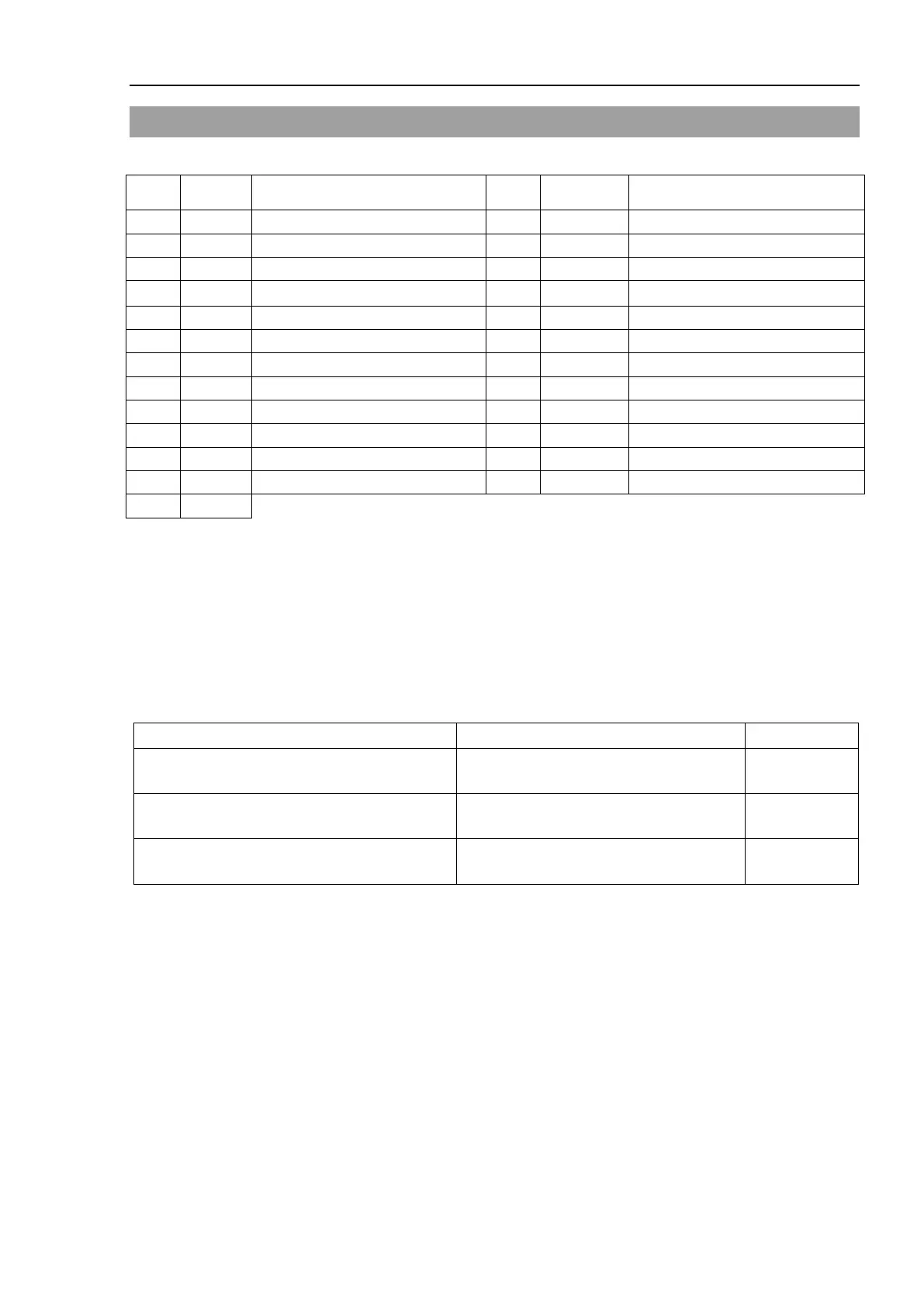
8.3 Pin Assignments
The EMERGENCY connector pin assignments are as follows:
Pin No. Signal Function Pin No.
Signal Function
1 ESW11 Emergency Stop switch contact (1)
14 ESW21 Emergency Stop switch contact (2)
2 ESW12 Emergency Stop switch contact (1)
15 ESW22 Emergency Stop switch contact (2)
3 ESTOP1+ Emergency Stop circuit 1 (+) 16 ESTOP2+ Emergency Stop circuit 2 (+)
4
ESTOP1−
Emergency Stop circuit 1 (
)
17
ESTOP2−
Emergency Stop circuit 2 (
)
5 NC
18 SDLATCH1 Safety Door Latch Release
6 NC
19 SDLATCH2 Safety Door Latch Release
7 SD11 Safety Door input (1)
20 SD21 Safety Door input (2)
8 SD12 Safety Door input (1)
21 SD22 Safety Door input (2)
9 24V +24V output 22 24V +24V output
10 24V +24V output 23 24V +24V output
11 24VGND +24V GND output 24 24VGND +24V GND output
12 24VGND +24V GND output 25 24VGND +24V GND output
13 NC
*1 Do not connect anything to these pins.
*2 A critical error occurs if the input values from the Safety Door 1 and Safety Door 2
are different for two or more seconds. They must be connected to the same switch
with two sets of contacts.
*3 A critical error occurs if the input values from the Emergency Stop switch contact 1
and Emergency Stop switch contact 2 are different for two or more seconds. They
must be connected the same switch with two sets of contacts.
Emergency Stop switch output rated load +30 V 0.3 A or under 1-2, 14-15 pin
Emergency Stop rated input voltage range
Emergency Stop rated input current
+24 V ±10%
47.5mA +24 V input
3-4, 16-17 pin
Safety Door rated input voltage range
Safety Door rated input current
+24 V ±10%
10 mA/+24 V input
7-8, 20-21 pin
Latch Release rated input voltage range
Latch Release rated input current
+24 V ±10%
10 mA/+24 V input
18-19 pin
The total electrical resistance of the Emergency Stop switches and their circuit should be 1
Ω or less.