Setup & Operation 12. Option Slots
70 RC620 Rev.8
12.4.4 RS-232C Software Communication Setup (RS-232C)
Available communication settings are as follows.
Baud Rates 110, 300, 600, 1200, 2400, 4800, 9600,
14400, 19200, 38400, 57600, 115200
Refer to EPSON RC+ 6.0 Online Help or 11. RS-232C Communications for RS-232C
communication from the Robot application.
12.4.5 Communication Cable (RS-232C)
Prepare a communication cable as described in this section.
RS-232C Connector
(Controller side)
D-sub 9 male pin
Mounting style #4 - 40
Use twisted pair cable for shielded wire.
Clamp the shield to the hood for noise prevention.
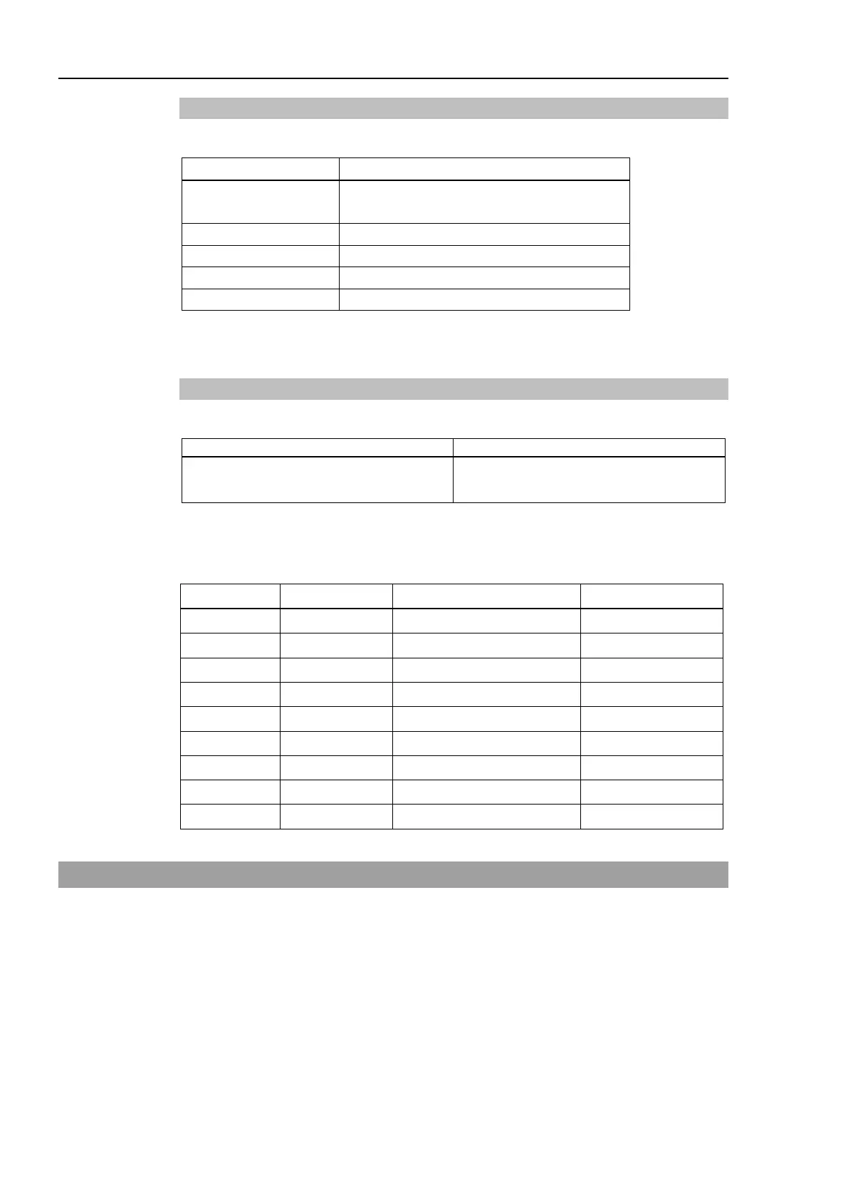
Pin assign of the RS-232C connector is as follows.
Pin No Signal Function Signal Direction
1 DCD Data carrier detect Input
2 RXD Receive data Input
3 TXD Send data Output
4 DTR Terminal ready Output
5 GND Signal ground -
6 DSR Data set ready Input
7 RTS Request to send Output
8 CTS Clear to send Input
9 RI Ring indicator Input
12.5 PG Board
The PG board is used in the following 2 methods. For the details, refer to the each
manual.
- When used as the conveyor encoder
Refer to the EPSON RC+ 6.0 Users Guide 15. Conveyor Tracking.
- When used as the PG motion system
Refer to the RC620 Robot Controller option PG Motion System manual.