ENABLING SWITCH
Using the ENABLING SWITCH function block the status
of the inputs for a 3-stage enabling switch is checked.
If this switch is not pressed (position 1) or is fully
pressed (position 3), the OUTPUT output is "0" (FALSE).
In the middle position (position 2) the OUTPUT output
is "1" (TRUE).
See truth table at the bottom of the page.
For the ENABLING SWITCH function block the
module assigned must have the firmware ver-
sion as shown in the table below, as a minimum:
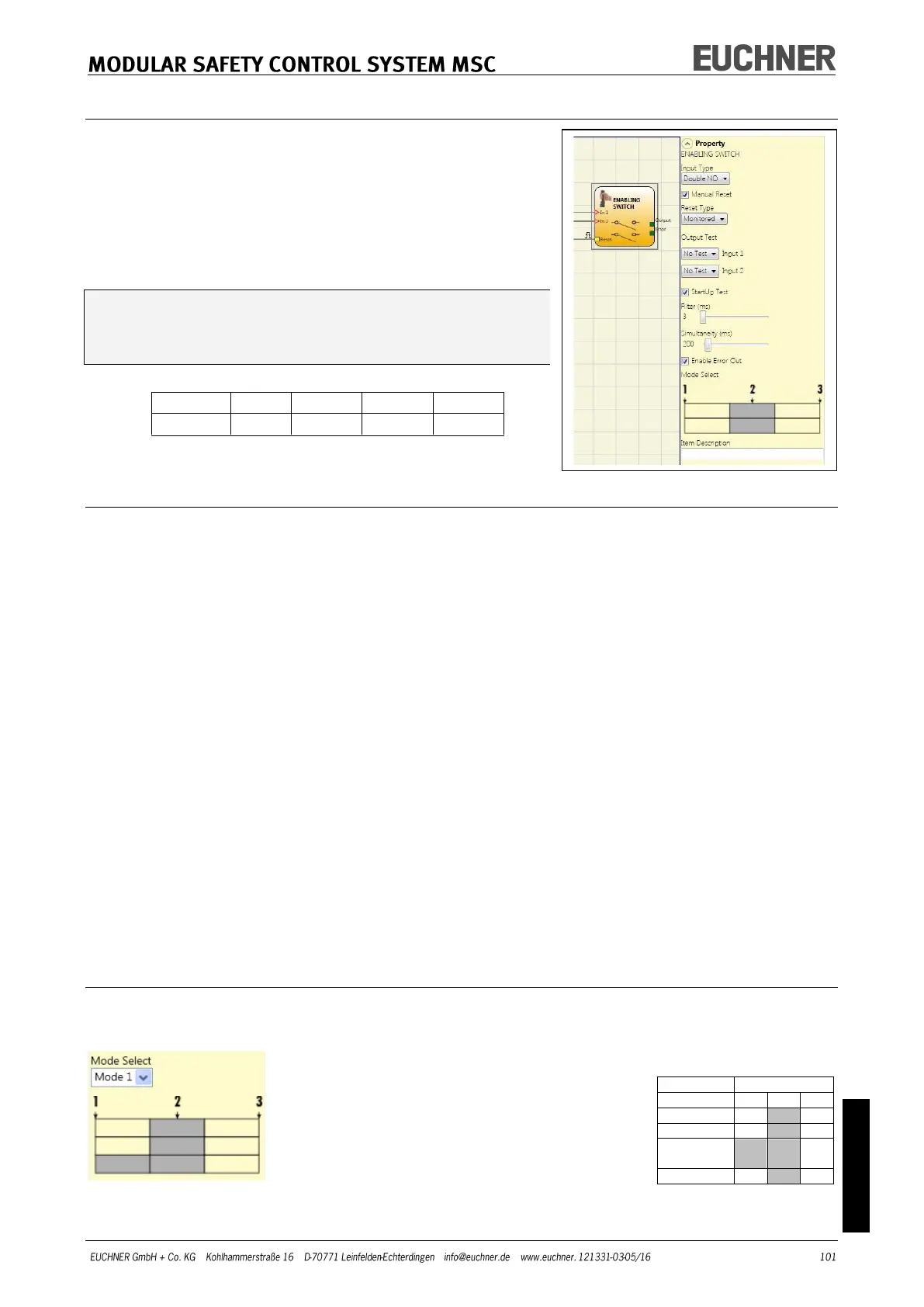
Parameters
Input Type:
- Double NO – makes it possible to connect an enabling switch with two normally
open contacts.
- Double NO + 1 NC – makes it possible to connect an enabling switch with two
normally open contacts and one normally closed contact.
Output Test: Makes it possible to select the test output signals that are to be sent to the
enabling switch.
Short circuits between the wires can be detected and rectified by means of this additional
check. For this purpose it is necessary to configure the test output signals (from the test
output signals available).
StartUp Test: If selected, the test is undertaken on switching on the external components
(enabling switch). This test is undertaken by pressing and releasing the switch to carry
out one complete function test and to activate the output. This test is only requested on
starting the machine (switching on the module).
Simultaneity (ms): always active. Defines the maximum permissible time (ms) between the
switching of the different signals that are received from the external contacts on the de-
vice.
Filter (ms): This parameter makes it possible to filter the signals from the device. The fil-
ter can be set to between 3 and 250 ms and removes any contact bounce. The time set
for the filter affects the calculation of the total response time of the module.
Table – Mode 1 (device with 2 NO + 1 NC)
POSITION 1: Enabling switch fully released
POSITION 2: Enabling switch pressed to center position
POSITION 3: Enabling switch pressed all the way down
(only with 2 NO contacts + 1 NC
contact)