The Stand still and speed control function block checks
the speed of a device; the ZERO output is "1" if the speed
is 0. In addition, the OVER output is "0" (FALSE) if the
speed measured exceeds a previously defined limit.
Parameters
Axis type: Defines the type of axis that is monitored by
the device. "Linear" if the movement is linear or „Rotation-
al“ if the movement is rotary.
Sensor type: If "Linear" is selected for the previous pa-
rameter, the sensor type connected to the inputs of the
module is defined here. „Rotational“ (e.g. Encoder on a
toothed rack) or "Linear" (e.g. optical linear sensor).
This selection defines the other parameters.
Measuring device: Defines the type of measuring devic-
es/sensors used. The following can be selected:
- Encoder
- Proximity
- Encoder + Proximity
- Proximity 1 + Proximity 2
- Encoder 1 + Encoder 2
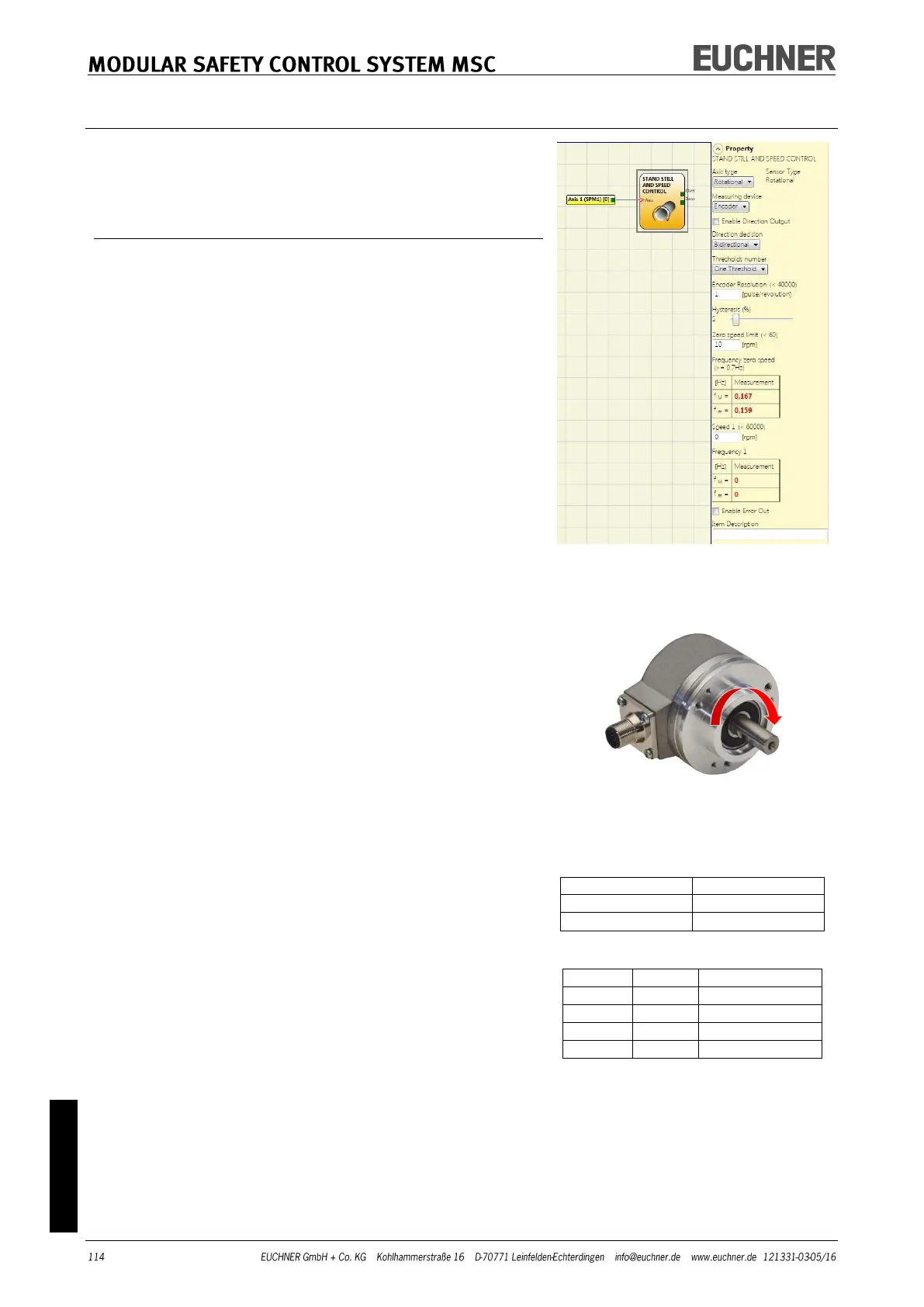
Enable direction output: Select this parameter to activate
the DIR output on the function block. This output is "1"
(TRUE) if the axis is rotating counter clockwise and "0"
(FALSE) if the axis is rotating clockwise.
(-> Figure on the right).
Direction decision: Defines the direction of rotation for
which the limits entered are activated. The following can
be selected:
- Bidirectional
- Clockwise
- Counterclockwise
If "Bidirectional" is selected, the measurement is made on
exceeding the limit entered, both clockwise and counter
clockwise.
If "Clockwise" or "Counterclockwise" is selected, the meas-
urement is only made if the axis is rotating in the selected
direction.
Thresholds number: Number of max. speed limits. By
changing this value the number of limits is in-
creased/reduced from at least 1 to a maximum of 4. If the
value selected is greater than 1, the input pins for the se-
lection of the specific limit appear in the bottom part of
the function block.
Pitch: If the axis type "Linear" and the sensor type „Rota-
tional“ are selected, this field enables you to enter the
pitch for converting the rotation of the sensor into the dis-
tance covered.