Proximity switch input on speed monitoring modules SPM
Configuration with combined proximity switches on one axis (Figure 5)
The SPM module can be configured in the "Combined proximity switch" mode for a
measurement using two proximity switches on one axis.
The Performance Level PLe can be achieved under the following conditions:
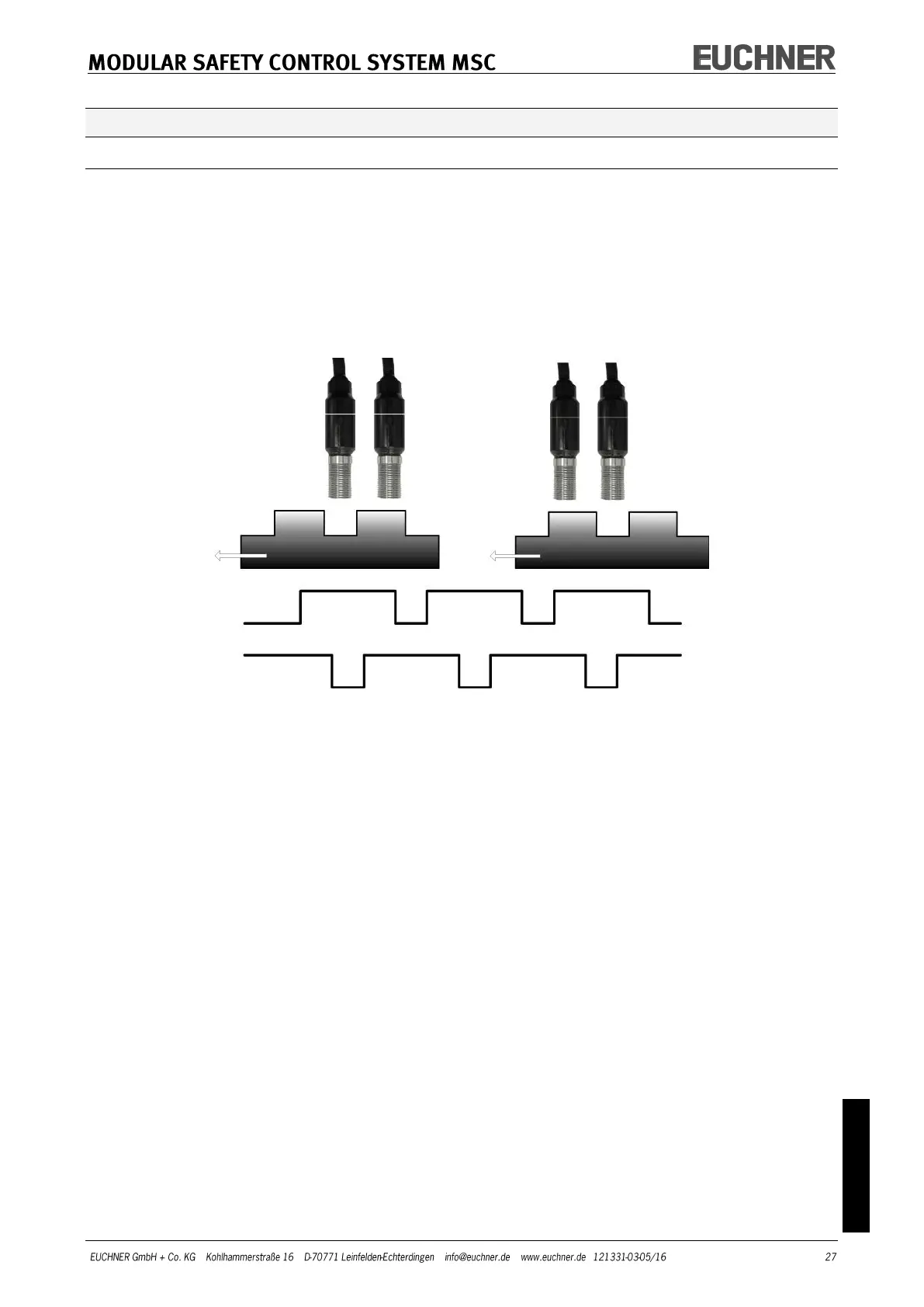
The proximity switches must be mounted such that the signals produced overlap.
The proximity switches must be mounted such that at least one proximity switch is
always actuated (active).
Figure 6
Additional information:
Proximity switches with a PNP output must be used.
Proximity switches with a normally open output (NO, output active if switch actuat-
ed) must be used.
In the conditions stated above the DC is 90%
Both proximity switches must be of the same type with a MTTF > 70 years.