Preparing the diagram
After the selection of the system layout, you can configure the project.
The logic diagram is prepared with the aid of the DRAG & DROP function:
• Select the objects required from the windows described above (the individual objects
are described in more detail in the following) and drag to the design workspace.
• After the selection of an object, the PROPERTY window is activated where you must
complete the fields as necessary.
• You can set a specific numeric value on a slider (e.g. Filter) using the left and right ar-
row keys on the keyboard, or by clicking on the ends of the slider.
• Objects can be linked together by selecting the required pin using the mouse and then
dropping the link on the pin to be connected using Drag & Drop.
• If the PAN function (panning workspace in the window) is needed, select object to be
panned and pan using the arrow keys on the keyboard.
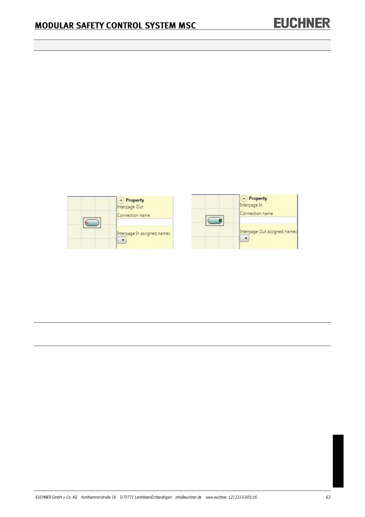
• You can make connections between elements a long way apart using the "Interpage
In/Out" in "Operator/Miscellaneous" component. The "Interpage Out" element must be
assigned a name that corresponds to the related "Interpage In" element to establish the
required connection.
Figure 35
• If an object needs to be duplicated, first you must select it and then you can copy and
paste it by pressing CTRL+C/CTRL+V on the keyboard.
• An object or a link is deleted by selecting the object or the link and then pressing DEL
on the keyboard.
Using the right mouse button
On input/output blocks
Copy/paste
Delete
Delete all assigned connections
Alignment with other function blocks (with multiple selection)
Help
Monitor mode: show/hide the property window
Status block: activate/deactivate the negation on the input pin