The speed control function block checks the speed of a de-
vice; the OVER output is "0" (FALSE) if the speed measured ex-
ceeds a previously defined limit. If the speed is below this pre-
defined limit, the OVER output is "1" (TRUE).
Parameters
Axis type: Defines the type of axis that is monitored by the
device. "Linear" if the movement is linear or „Rotational“ if the
movement is rotary.
Sensor type: If "Linear" is selected for the previous parameter,
the sensor type connected to the inputs of the module is de-
fined here. „Rotational“ (e.g. Encoder on a toothed rack) or
"Linear" (e.g. optical linear sensor).
This selection defines the other parameters.
Measuring device: Defines the type of measuring devic-
es/sensors used. The following can be selected:
- Encoder
- Proximity
- Encoder + Proximity
- Proximity 1 + Proximity 2
- Encoder 1 + Encoder 2
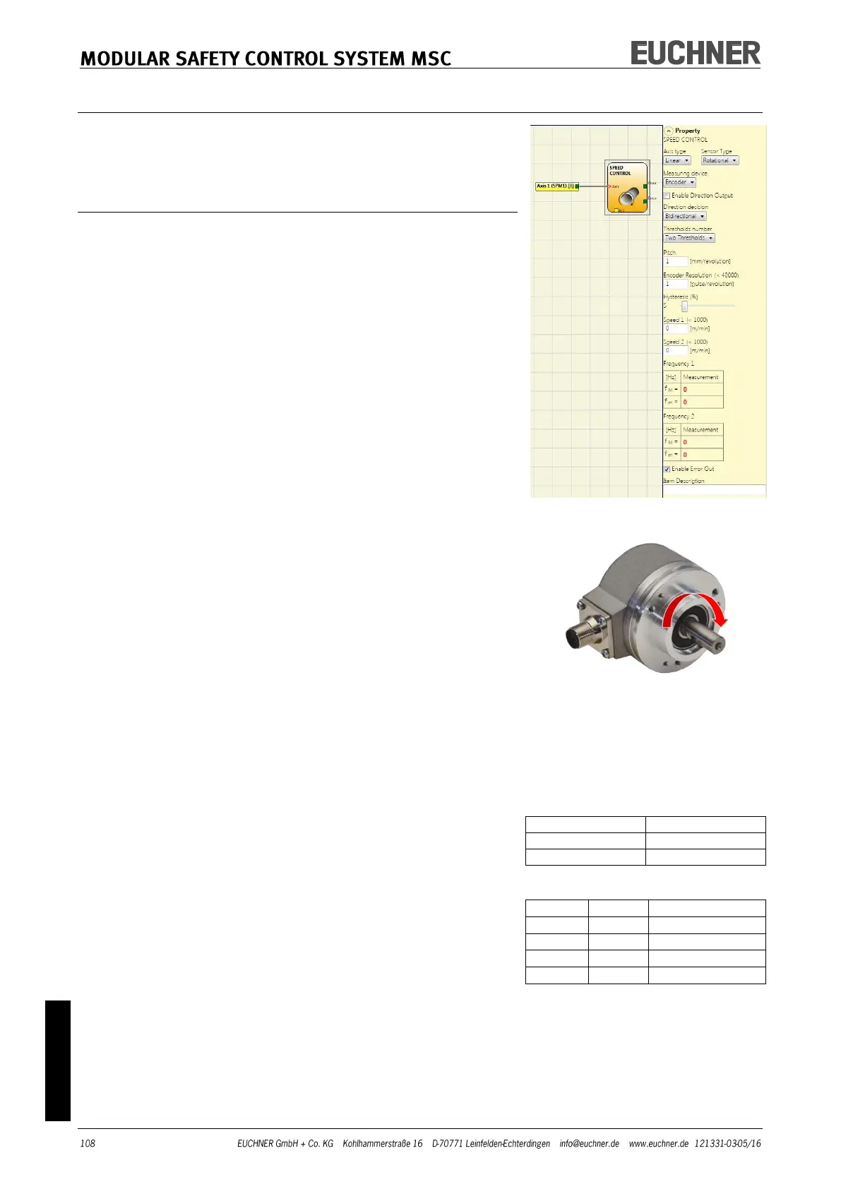
Enable direction output: Select this parameter to activate the
DIR output on the function block. This output is "1" (TRUE) if
the axis is rotating counter clockwise and "0" (FALSE) if the ax-
is is rotating clockwise. (-> Figure on the right).
Direction decision: Defines the direction of rotation for which
the limits entered are activated. The following can be selected:
- Bidirectional
- Clockwise
- Counterclockwise
If "Bidirectional" is selected, the measurement is made on ex-
ceeding the limit entered, both clockwise and counter clock-
wise.
If "Clockwise" or "Counterclockwise" is selected, the measure-
ment is only made if the axis is rotating in the selected direc-
tion.
Thresholds number: Number of max. speed limits. By chang-
ing this value the number of limits is increased/reduced from
at least 1 to a maximum of 4. If the value selected is greater
than 1, the input pins for the selection of the specific limit ap-
pear in the bottom part of the function block.