The Window speed control function block checks the speed of
a device; the WINDOW output is "1" (TRUE) if the speed meas-
ured is within the previously defined speed window.
Parameters
Axis type: Defines the type of axis that is monitored by the
device. "Linear" if the movement is linear or „Rotational“ if the
movement is rotary.
Sensor type: If "Linear" is selected for the previous parameter,
the sensor type connected to the inputs of the module is de-
fined here. „Rotational“ (e.g. Encoder on a toothed rack) or
"Linear" (e.g. optical linear sensor).
This selection defines the other parameters.
Measuring device: Defines the type of measuring devic-
es/sensors used. The following can be selected:
- Encoder
- Proximity
- Encoder + Proximity
- Proximity 1 + Proximity 2
- Encoder 1 + Encoder 2
Pitch: If the axis type "Linear" and the sensor type „Rotational“
are selected, this field becomes active. Enter here the distance
that is covered during one sensor revolution.
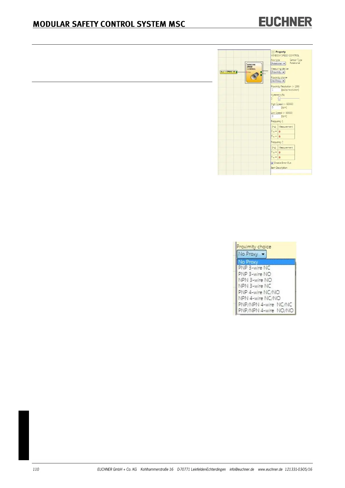
Proximity choice: Selecting the proximity switch enables you
to select between PNP, NPN, NO contact, NC contact, 3-wire or
4-wire.
(To ensure Performance Level=Ple, a PNP NO contact must be used
(see "Proximity switch input on speed monitoring modules SPM", page
27).
Resolution: Entry for the number of pulses/revolution (for a
rotary sensor) or μm/pulse (for a linear sensor) in relation to
the 1st measuring device.
Verification: Entry for the number of pulses/revolution (for a
rotary sensor) or μm/pulse (for a linear sensor) in relation to
the 2nd measuring device.