OUTPUTS
OUT_STATUS
The OUT_STATUS signal is a programmable digital output for the indication of the state
of:
• An input
• An output
• A node on the logic diagram that has been designed with the aid of the software
EUCHNER Safety Designer.
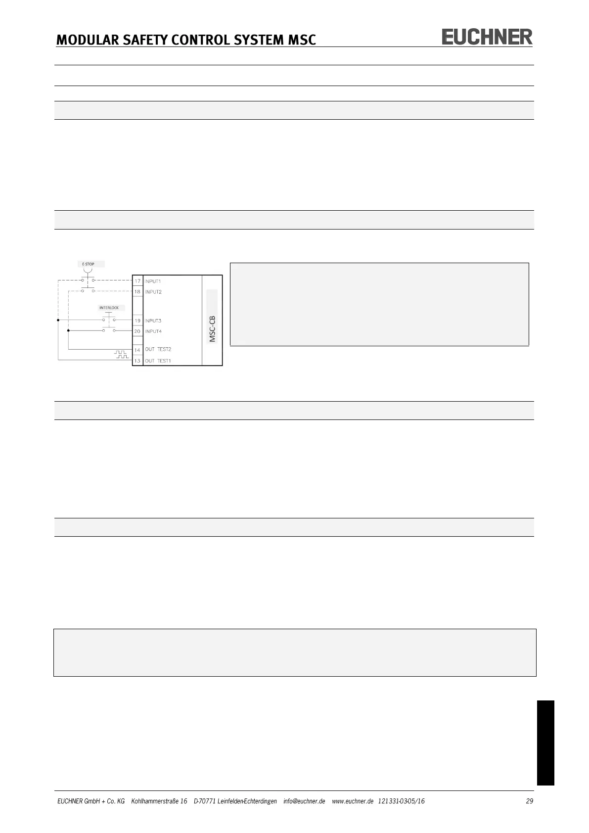
OUT_TEST
The inputs and the cables can be monitored for short circuits or overload states using the
OUT_TEST signals (Figure 7).
The maximum number of inputs that can be controlled by
each OUT_TEST output:
- 2 INPUTS (parallel connection) (MSC-CB, FI8FO2, FI8, FM4)
- 4 INPUTS (parallel connection) (FI16)
The maximum permissible length of the cable on the
OUT_TEST output is 100 m.
Figure 7
OSSD (MSC-CB, FI8FO2)
The OSSD outputs (Output Signal Switching Device) are short-circuit proof, monitored for
cross circuit and supply:
• In the ON state: Uv -0.75 V – Uv (where Uv = 24 V ± 20 %)
• In the OFF state: 0–2 V eff.
The maximum load of 400 mA @ 24 V corresponds to a minimum ohmic load of 60 .
The maximum capacitive load is 0.82 F, the maximum inductive load 30 mH.
OSSD (AC-FO2, AC-FO4)
The OSSD outputs (Output Signal Switching Device) are short-circuit proof, monitored for
cross circuit and supply:
• In the ON state: Uv -0.75 V – Uv (where Uv = 24 V ± 20 %)
• In the OFF state: 0–2 V eff.
The maximum load of 400 mA @ 24 V corresponds to a minimum ohmic load of 60 .
The maximum capacitive load is 0.82 F, the maximum inductive load 30 mH.
It is not allowed to connect external devices to the outputs, except if this arrange-
ment is foreseen in the configuration undertaken in the software EUCHNER Safety
Designer.
Each OSSD output can be configured as shown in Table 14: