EasyManua.ls Logo

EUCHNER MSC - Example for the Connection of the MSC System to the Machine Control

EUCHNER MSC
148 pages
Print Icon
To Next Page IconTo Next Page
To Previous Page IconTo Previous Page
Loading...
English
AZ-FO4O8
TERMINAL
SIGNAL
TYPE
DESCRIPTION
OPERATION
1
24 VDC
-
Power supply 24 VDC
-
2
NODE_SEL1
Input
Node selection
Input ("type B" as per
EN 61131-2)
3
NODE_SEL2
Input
Input ("type B" as per
EN 61131-2)
4
0 VDC
-
Power supply 0 VDC
-
5
REST_FBK1
Input
Feedback loop/restart 1
Input (as per EN 61131-2)
6
REST_FBK2
Input
Feedback loop/restart 2
Input (as per EN 61131-2)
7
REST_FBK3
Input
Feedback loop/restart 3
Input (as per EN 61131-2)
8
REST_FBK4
Input
Feedback loop/restart 4
Input (as per EN 61131-2)
9
A_NO1
Output
Normally open contact channel 1
10
B_NO1
Output
11
A_NO2
Output
Normally open contact channel 2
12
B_NO2
Output
13
A_NO3
Output
Normally open contact channel 3
14
B_NO3
Output
15
A_NO4
Output
Normally open contact channel 4
16
B_NO4
Output
17
SYS_STATUS1
Output
Programmable digital output 1
PNP active high
18
SYS_STATUS2
Output
Programmable digital output 2
PNP active high
19
SYS_STATUS3
Output
Programmable digital output 3
PNP active high
20
SYS_STATUS4
Output
Programmable digital output 4
PNP active high
21
SYS_STATUS5
Output
Programmable digital output 5
PNP active high
22
SYS_STATUS6
Output
Programmable digital output 6
PNP active high
23
SYS_STATUS7
Output
Programmable digital output 7
PNP active high
24
SYS_STATUS8
Output
Programmable digital output 8
PNP active high
Table 11
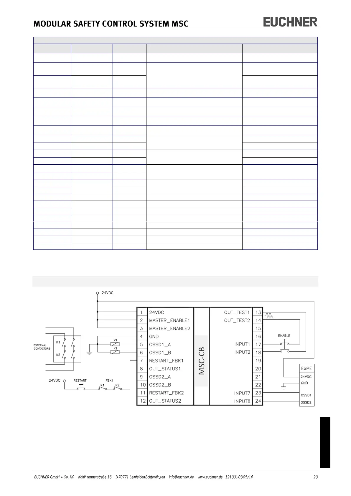
Example for the connection of the MSC system to the machine control
Figure 5

Table of Contents

Other manuals for EUCHNER MSC