STAND STILL
The Stand still function block checks the speed of a device;
the ZERO output is "1" (TRUE) if the speed is 0. If the speed is
not 0, the ZERO output is "0" (FALSE).
Parameters
Axis type: Defines the type of axis that is monitored by the
device. "Linear" if the movement is linear or „Rotational“ if the
movement is rotary.
Sensor type: If "Linear" is selected for the previous parame-
ter, the sensor type connected to the inputs of the module is
defined here. „Rotational“ (e.g. Encoder on a toothed rack) or
"Linear" (e.g. optical linear sensor).
This selection defines the other parameters.
Measuring device: Defines the type of measuring devic-
es/sensors used. The following can be selected:
- Encoder
- Proximity
- Encoder + Proximity
- Proximity 1 + Proximity 2
- Encoder 1 + Encoder 2
Pitch: If the axis type "Linear" and the sensor type „Rotation-
al“ are selected, this field becomes active. Enter here the dis-
tance that is covered during one sensor revolution.
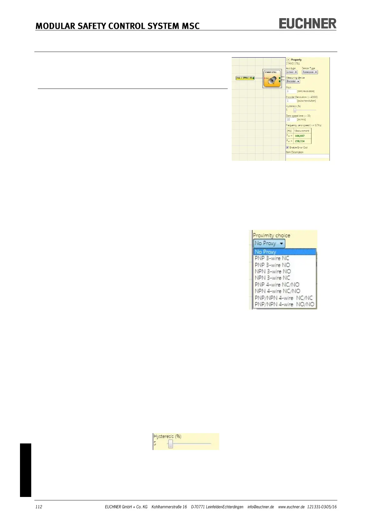
Proximity choice: Selecting the proximity switch enables you
to select between PNP, NPN, NO contact, NC contact, 3-wire
or 4-wire.
(To ensure Performance Level=Ple, a PNP NO contact must be used
(see "Proximity switch input on speed monitoring modules SPM",
page 27).
Resolution: Entry for the number of pulses/revolution (for a rotary sensor) or μm/pulse (for a
linear sensor) in relation to the 1st measuring device.
Verification: Entry for the number of pulses/revolution (for a rotary sensor) or μm/pulse (for a
linear sensor) in relation to the 2nd measuring device.
Gear ratio: This parameter is active if there are two sensors on the selected axis. This parame-
ter enables you to enter the gear ratio between the two sensors. If the two sensors are on the
same moving object, the ratio is 1, otherwise the figure for the ratio must be entered. Example:
There is an Encoder and a proximity switch and the latter is on the moving object that (due to a
gear ratio) moves at twice the speed in relation to the Encoder. The value 2 is therefore entered.
Hysteresis (%): Represents the hysteresis (in percent) below which the speed change is filtered
out. Enter a value other than 1 to prevent continuous switching of the input.
Zero speed limit: Enter in this field the maximum speed that is still corresponds to standstill.
Above this limit the ZERO output on the function block is "0" (FALSE). Conversely, if the speed
measured is below the value entered, the ZERO output on the function block is "1" (TRUE).