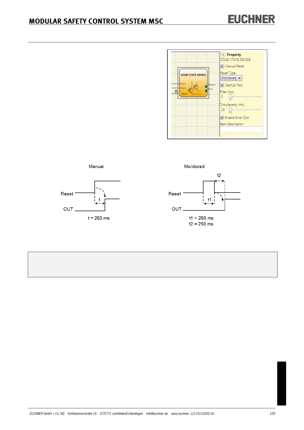
SOLID STATE DEVICE
Using the SOLID STATE DEVICE function block
the status of the inputs is checked. If 24 VDC
are present on the inputs, the OUTPUT output
switches to "1" (TRUE), otherwise the OUTPUT
output is "0" (FALSE).
Parameters
Manual Reset: If selected, a reset can be re-
quested on every activation of the safety func-
tion. Otherwise the activation of the output will
correspond directly to the input conditions.
There are two types of reset: "Manual" and "Mon-
itored". On the selection of the manual reset, the
system only checks the signal transition from 0 to 1. With the monitored reset the double
transition from 0 to 1 and then back to 0 is checked.
WARNING: If reset is activated, the input after the inputs used by the function block
must be used. Example: If Input1 and Input2 are used for the function block, Input3
must be used for the reset.
StartUp Test: If selected, the test is undertaken on switching on the safety device. This
test requires the activation and deactivation of the device to carry out one complete func-
tion test and to activate the output. This test is only requested on starting the machine
(switching on the module).
Filter (ms): This parameter makes it possible to filter the signals from the safety device.
The filter can be set to between 3 and 250 ms and removes any contact bounce. The time
set for the filter affects the calculation of the total response time of the module.
Simultaneity (ms): Defines the maximum permissible time (ms) between the switching of
the two different signals that are received from the device.
Enable Error Out: If selected, an error detected by the function block is signaled.
Item Description: Makes it possible to add a functional description of the component.
This text is displayed in the upper part of the symbol.