OTHER FUNCTION BLOCKS
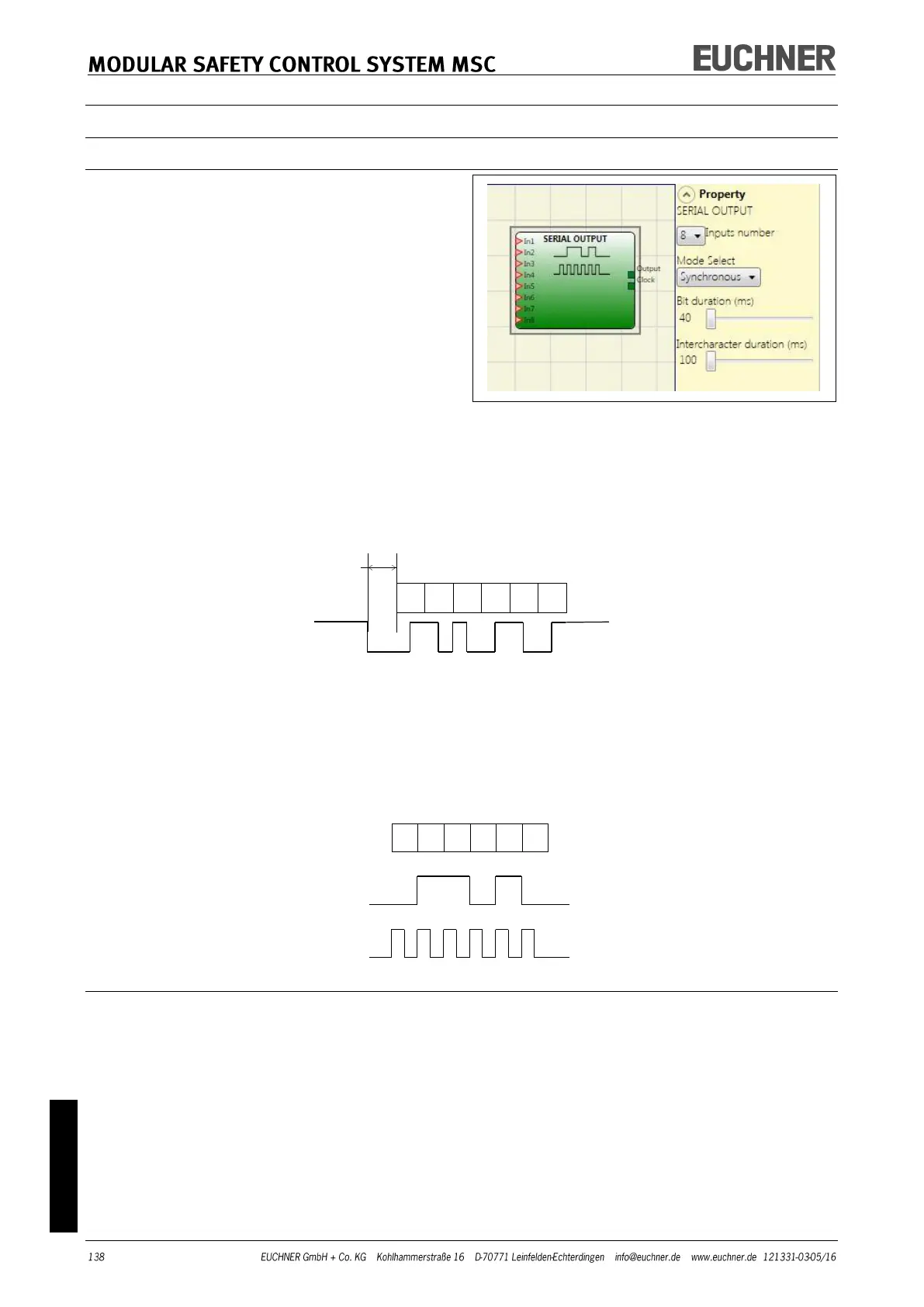
SERIAL OUTPUT
Using the SERIAL OUTPUT operator the status of
up to 8 sensors is output; the data are output in
series.
Principle of operation
Using this operator the status of all inputs con-
nected is output in two different ways:
Asynchronous serial output:
1) The status on the cable when not in use is "1" (TRUE).
2) The start data transfer signal is 1 bit = (FALSE).
3) Transfer of n bits, where the status of the inputs connected is Manchester coded:
- Status 0: rising signal edge in the middle of the bit
- Status 1: falling signal edge in the middle of the bit
4) Intercharacter interval is "1" (TRUE) to make it possible to synchronize an external device.
For this reason the Clock output is not available with the asynchronous method.
Synchronous serial output:
1) Output and Clock are "0" (FALSE) when not in use.
2) Transfer of n bits, where the input status is coded with OUTPUT as data and CLOCK as time-
base.
3) Intercharacter interval is "0" (FALSE) to make it possible to synchronize an external device.
Parameters
Inputs number: Defines the number of inputs on the function block. These can be 2 to 8 (asyn-
chronous) or 3 to 8 (synchronous).
Bit duration (ms): Here you can enter the value that corresponds to the length of the individual
bits (input n) in the pulse sequence that comprises the transmission.
- 40 ms to 200 ms (10 ms step)
- 250 ms to 0.95 s (50 ms step)
Intercharacter duration (ms): Enter here the time that must elapse between the transmission of
one pulse sequence and the next.
- 100 ms to 2.5 s (100 ms step)
- 3 s to 6 s (500 ms step)