Example for a project
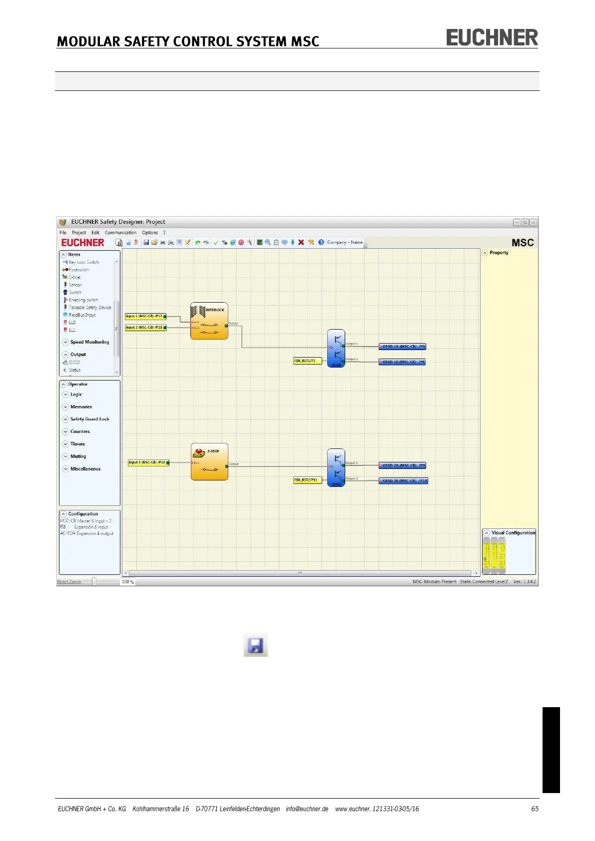
Figure 37 shows an example of a project in which the module MSC-CB is connected to on-
ly two safety components (INTERLOCK and E-STOP).
The inputs (1, 2, 3) on the module MSC-CB for connecting the contacts on the safety
components are highlighted in yellow on the left. The MSC outputs (from 1 to 4) are acti-
vated as per the conditions that are defined in INTERLOCK and E-STOP (see page 81 E–
STOP and page 83 INTERLOCK).
Click a block to select it and activate the PROPERTY window on the right where you can
configure the activation and test parameters for the block.
Figure 37
At the end of the project preparation phase (or during intermediate steps), you can save
the actual configuration using the button on the default toolbar.