EasyManua.ls Logo

EUCHNER MSC - 9.2.2.19. Semiconductor output (SOLID STATE DEVICE)

EUCHNER MSC
148 pages
Print Icon
To Next Page IconTo Next Page
To Previous Page IconTo Previous Page
Loading...
English
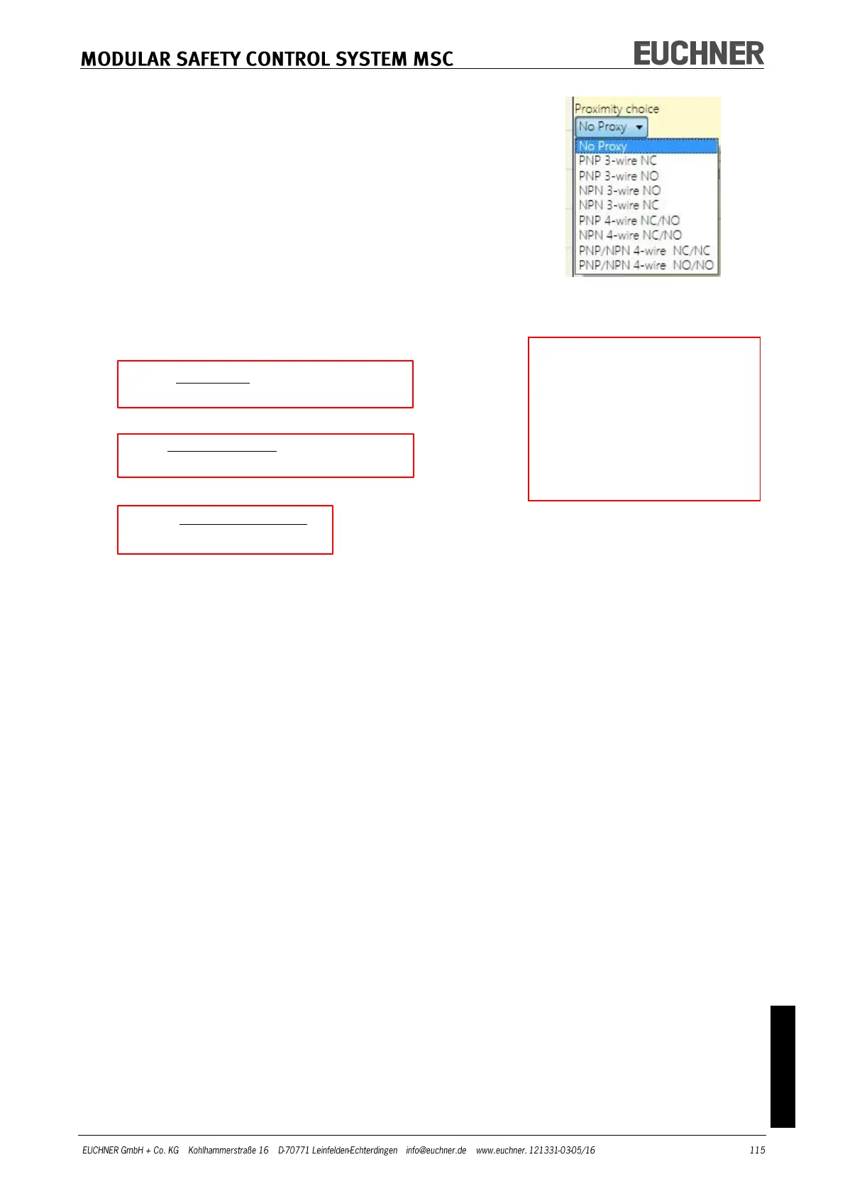
Proximity choice: Selecting the proximity switch enables you
to select between PNP, NPN, NO contact, NC contact, 3-wire
or 4-wire.
(To ensure Performance Level=Ple, a PNP NO contact must be used
(see "Proximity switch input on speed monitoring modules SPM",
page 27).
Standstill frequency / Frequency 1 / Frequency 2:
Defines the calculated values for the maximum frequency fM
and fm (reduced by the hysteresis entered). If the value dis-
played is GREEN, the calculated frequency is in the correct
range. If the value displayed is RED, the parameters given in
the following formula must be changed.
1. Rotary axis, rotary sensor. The calculated frequency is:
v][pulses/resolutionRe
60
[rev/min]rpm
[Hz]f
2. Linear axis, rotary sensor. The calculated frequency is:
v][pulses/reRe
[mm/rev]*60
1000*[m/min]
[Hz] solution
pitch
speed
f
3. Linear axis, linear sensor. The calculated frequency is:
m/pulse]solutionRe
1000*[mm/s]speed
[Hz]f
4. Hysteresis. Only to be changed if: fM = green; fm = red
Selection of Proximity
KEY:
f = Frequency
Rpm = Rotary speed
Resolution = Resolution
Speed = Linear speed
Pitch = Pitch

Table of Contents

Other manuals for EUCHNER MSC