CHAPTER 27
PAGE 9
PAGE DATE: 1. March 2011
MAINTENANCE MANUAL EXTRA 330LX
27-00-02 Bellcranks
Removal/Installation
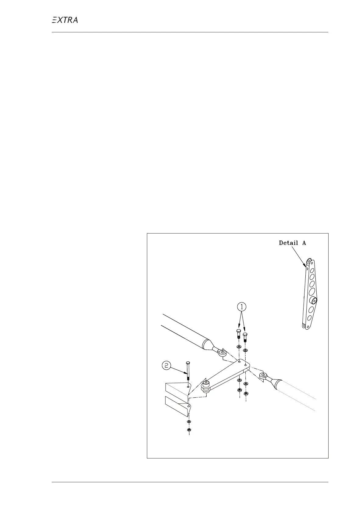
Refer to Figure 8
1 Remove the respective access panels.
2 Remove the adjacent control rods per chapter 27-00-01.
3 Remove the M5 attachment bolt (2).
4 Remove the bellcrank.
5 Reverse procedure to install the bellcrank using sufficient
washers (min. 2) at the nut side of the bolt to cover the shank
(except the rocker type bellcrank: use only one washer on
each side). Replace the selflocking nuts. Observe the first
note of chapter 27-00-00. To ensure installation of the el-
evator rocker type bellcrank in correct direction this bell-
crank is marked by an "F" which indicates the front side (re-
fer to detail A of figure 8).
Figure 8 Control Levers and Rods Removal/Installation