CHAPTER 77
PAGE 11
MAINTENANCE MANUAL EXTRA 330LX
PAGE DATE: 14. August 2015
Instrument Panel Layout
Generally an alternate panel is used to carry the MVP-50P.
For that reason the circuit breaker layout also changes as
shown in Figure 3.
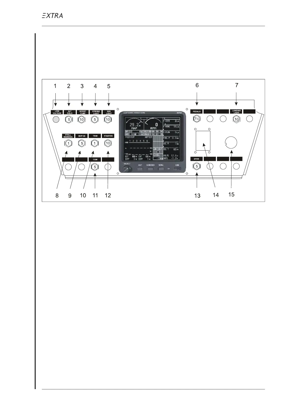
Figure 3 Alternate Panel Layout
Pos.Item
1 Alternator warning light incl. press-to-test feature
(located in the switch-row, if sub panel is not used)
2 Alternator field circuit breaker
3 Boost pump circuit breaker
4 Strobe light circuit breaker
5 NAV light circuit breaker
6 Electrical pedal adjustment circuit breaker
7 Landing light circuit breaker
8 Stall warning circuit breaker
9 MVP-50 circuit breaker
10 Electrical trim system circuit breaker
11 COM circuit breaker
12 Starter circuit breaker
13 Transponder circuit breaker
14 ELT Switch
15 Starter switch