CHAPTER 31
PAGE 7
PAGE DATE: 1. March 2011
MAINTENANCE MANUAL EXTRA 330LX
31-10-02 Front Instrument Panel
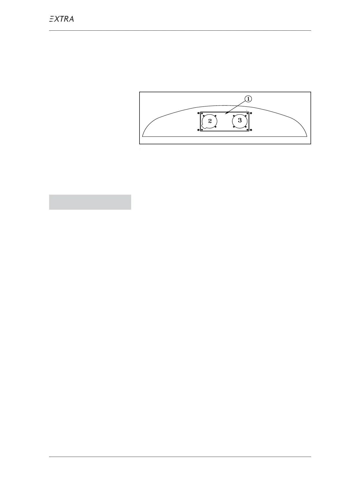
An altimeter and airspeed indicator (2, 3, figure 3) are
installed on a separate removable instrument panel (1) in the
main fuselage cover in front of the front pilot.
Figure 3 Front Instrument Panel
Removal/Installation
N O T I C E Hold instruments and panel by hand to prevent from
falling down when removing the instrument panel at-
tachment screws.
1 Remove the AN526 C-1032-R6 instrument panel attachment
screws (3, figure 4).
2 Disconnect the Pitot resp. static lines from the instruments
(7). Mark lines for later identification.
3 Remove instrument panel (5) and frame (6).
4 Remove DIN 912 M4x20 screws (4) if removal of instru-
ments is necessary.
5 Remove DIN 912 M4x5 bolts (2) and shock mounts (1) with
LN 9348 M4 stop nuts for disassembly of instrument panel
and frame.
6 Reverse procedure for assembly/installation.