Chapter 4 Installation and Wiring
PAGE 4-50
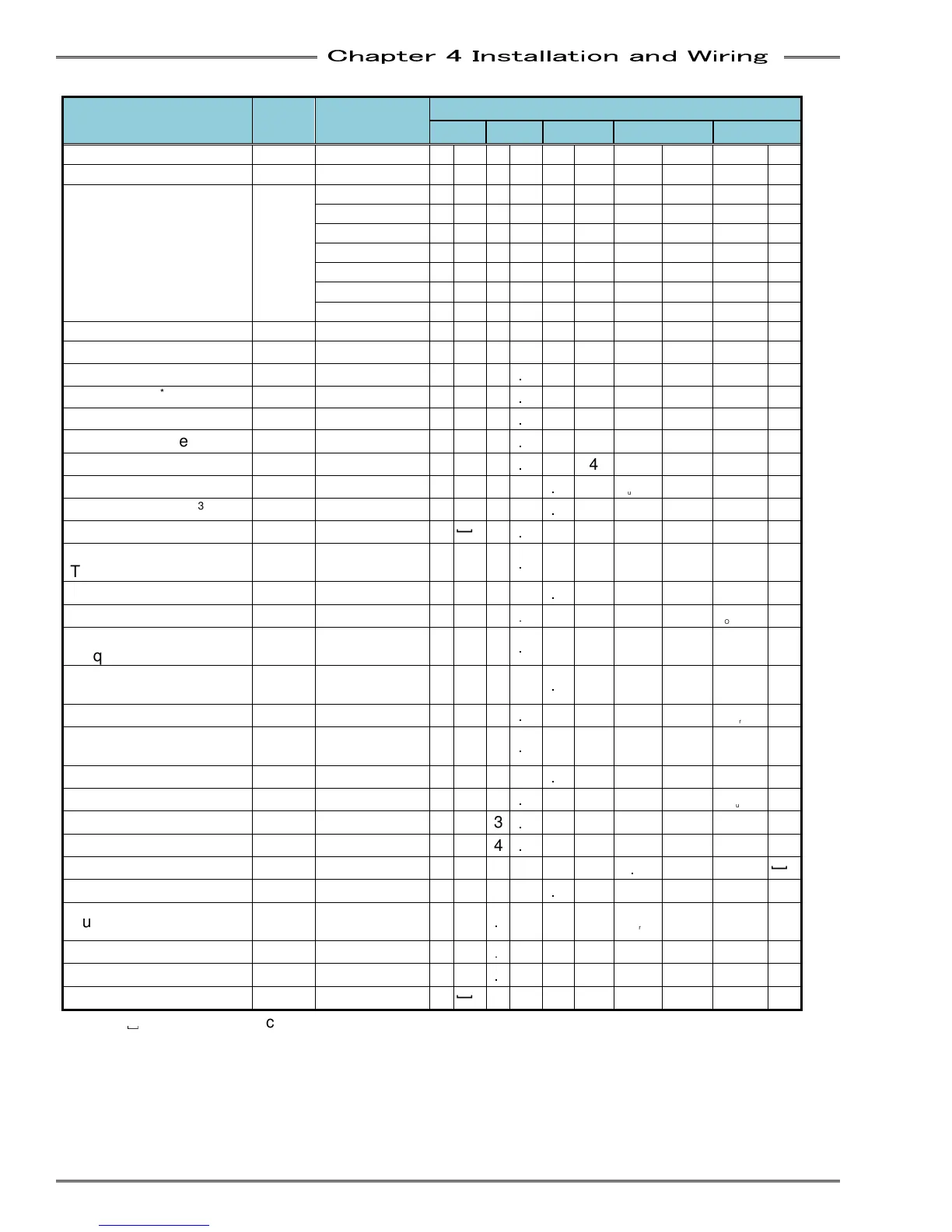
• Spindle data output format
Output Items
Number
of
Bytes
Fastening
Data
Axis Format
1word 2word
3word 4word 5word
Spindle No. (1 to 32)
2 1
1
PAR No. (1 to 32) 2 2
2
Spindle Judgment
*2
4
REJECT R
E J
]
ACCEPT A
C C
]
ABNORMAL A
B N
]
STOP S
T O
P
RESET STOP
R
S T
]
BYPASS B
Y P
]
START OFF S
O F
F
Spindle Cycle Count 8 123456
]
1
2 3 4 5 6
TOOL Cycle Count 8 12345678 1
2 3
4 5 6 7 8
Peak Torque
*3
8 12.34
1 2
.
3 4
Judgment Occurrence
Final Torque
*3
8 12.34
1 2
.
3 4
Judgment
Occurrence
SNUG Torque
*3
8 5.67
]
5
.
6 7
Judgment
Occurrence
1st Peak Torque 6 12.34
1 2
.
3 4
2nd Peak Torque 6 12.34
1 2
.
3 4
Final Angle
*3
8 123.4
1 2
3
.
4
Judgment
Occurrence
Differential Angle
*3
8 -12.3 -
]
1
2
.
3
Judgment
Occurrence
Rate 1
*3
10 1.234
]
1
.
2 3 4
Judgment
Occurrence
]
Rate 1 Increment
Torque
6 12.34
1 2
.
3 4
Rate 1 Increment Angle 6 123.4
1 2
3
.
4
Rate 2
*3
10 -0.123 -
]
0
.
1 2 3
Judgment
Occurrence
]
Rate 2 Increment
Torque
*3
6 12.34
1 2
.
3 4
Rate 2 Increment
Angle
*3
6 123.4
1 2
3
.
4
Rate 3
*3
10 0.123
]
0
.
1 2 3
Judgment
Occurrence
]
Rate 3 Increment
Torque
6 12.34
1 2
.
3 4
Rate 3 Increment Angle 6 123.4
1 2
3
.
4
1st Time
*3
10 123.456 1
2 3
.
4 5 6
Judgment
Occurrence
]
2nd Time
*3
10 123.456 1
2 3
.
4 5 6
Judgment
Occurrence
]
Cycle Time
*3
8 654.321 6
5 4
.
3 2 1
]
Peak Current
*3
10 12.3
]
]
1 2
.
3
Warning
]
Angle at Peak Torque 6 123.4
1 2
3
.
4
Rundown Revolutions
*3
8 12.34 1
2
3 4
Judgme
nt
Occurrence
]
ZERO Voltage 6 -0.123 -
0
1 2 3
CAL Voltage 6 3.512
3
5 1 2
Load rate
4 20
]
2
0
*1: “
␣
” (20H) is the space code (space).
*2: Please refer to “Spindle Judgment” (above in Single System setup explanation) regarding the
details of the Spindle judgment.