Chapter 4 Installation and Wiring
PAGE 4-65
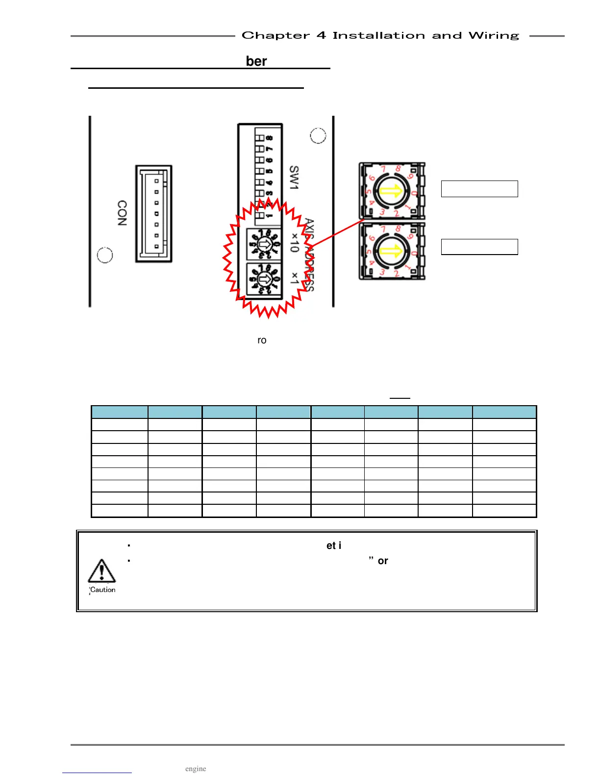
4-12 Setting Spindle Number Switches
4-12-1 Setting the Spindle No. Switch
Axis No. Switch Settings
The rotary switches on the controller front panel are used to set the axis no. of each unit. If the display is
mounted on the front of the controller, it must be removed to access the switches. Remove the indicator
by loosening the screws at 2 locations at the lower part of the display.
* Only change the axis no. setting with the control power OFF.
No. Setting No. Setting No. Setting No. Setting
01 1st Axis 09 9th Axis 17 17th Axis 25 25th Axis
02 2nd Axis 10 10th Axis 18 18th Axis 26 26th Axis
03 3rd Axis 11 11th Axis 19 19th Axis 27 27th Axis
04 4th Axis 12 12th Axis 20 20th Axis 28 28th Axis
05 5th Axis 13 13th Axis 21 21st Axis 29 29th Axis
06 6th Axis 14 14th Axis 22 22nd Axis
30 30th Axis
07 7th Axis 15 15th Axis 23 23rd Axis 31 31st Axis
08 8th Axis 16 16th Axis 24 24th Axis 32 32nd Axis
・
・・
・
The Axis No. of a controller cannot be set in duplicate.
・
・・
・
When the control power is turned ON with “00” or “33” -
Axis No., Abnormal A.09-
09 “Axis No. Setting Error” is generated. Turn OFF the
control power source and change the Axis No. in this case.
Tens
Caution