Chapter 4 Installation and Wiring
PAGE 4-66
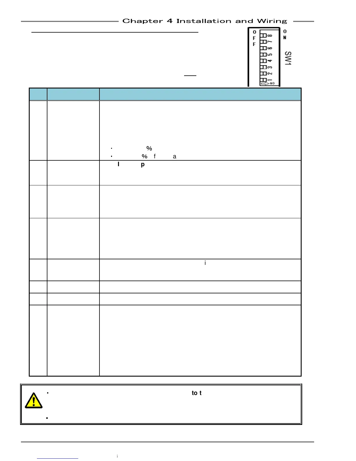
4-12-2 Setting the Special Function Switch - SW1
The SW1 switches on the Unit front panel are used to set special
functions related to fastening. To access the switch, remove the display
by unscrewing the two screws on the display and pulling the display from the
Controller.
* Only change the switch settings with the control power OFF.
No. Default Setting Setting Content
1 OFF
Zero Level Acceptance Window Selection
Selects the acceptable range of the torque transducer ZERO voltage
level during the Self Check of the Torque Transducer
Set this to ON if nuisance self-check abnormal’s (A1_3) occur
frequently at the start of cycle (due to outside forces or vibration on
the torque transducer)
・
ON …±10
%
of full scale torque
・
OFF …±4
%
of full scale torque
2 OFF
Start Input Type Selection
(STAND ALONE SINGLE MODE ONLY)
ON: Deadman Type – Start Input must remain on for the entire cycle
OFF: Auto Start Type – Start input pulse initiates automatic cycle
3 OFF
Disable Tool Cycle Count to Tool ID
Can be used in systems using tool changers where the tool cable is
frequently disconnected (reduces the possibility of Tool ID corruption)
OFF: Enable Tool Cycle Count to Tool ID
4 OFF
Analog Angle Output Pulse
Selects the number of angle pulses output from the external monitor
output (See 4-7 External Monitoring Interface)
ON : 0.1 deg per pulse
OFF: 1.0 deg per pulse
5 OFF
For standalone configuration only
ON: SYNC signals via Sensor2 connector – Pin 9 Sync In, Pin 13 Sync
out
6 OFF
7 OFF
8 OFF
If the switch is OFF when the power turns on, this spindle will operate
as a Slave spindle, and link communication will be via the MASTER
controller. (Slaves can be programmed via the MASTER using the
User Console software)
ON : Master Spindle Specification
If the switch is ON when the power turns on, this spindle will operate
as a Master spindle. Any slave spindles connected to it, will controlled
by the Master. Each Master in a system will require separate PLC
control and IP configuration for User Console connection.
・
・・
・
When changing a MFC unit, be sure to s
et SW8 to the same setting as the unit being
removed. (In a typical MULTI system, Spdl. #1 is set as MASTER and all other spdls. a
SLAVES
・
・・
・
For Multi System use, turn No.2 of SW1 to OFF.