Chapter 5
I/O
Expansion Unit
Page 5-5
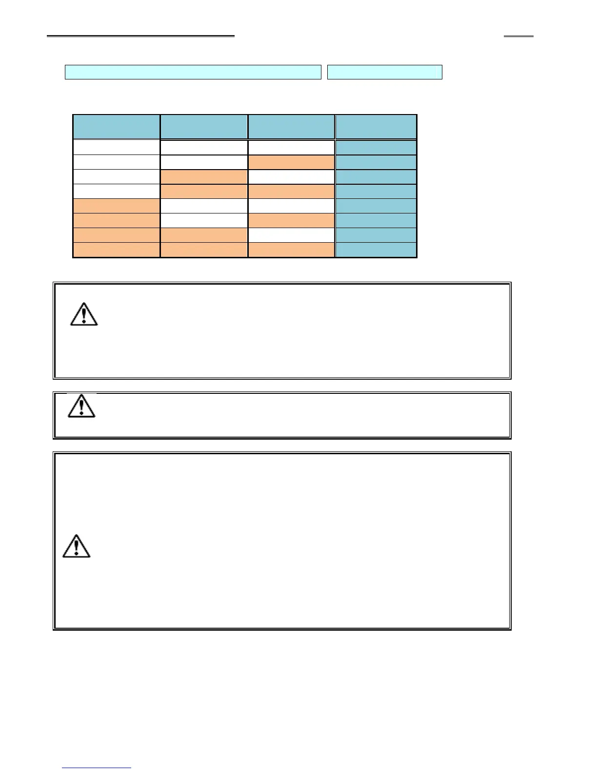
BANK SELECT 0 to 2: Bank Switching Signal Pin Nos.: 32, 33, 34
The output “bank” for output signal definition is changed by a combination of the BANK SELECT
signals as shown below. (Used by the Discrete I/O interface only – not used for fieldbus interfaces)
・ Set the BANK SELECT 0 to 2 signals to OFF during the fastening operation or
when it is not required.
・ Wait 20ms minimum before reading the OUTPUT status after changing the
BANK SELECT INPUT.
・ When Bank Switching is executed, the contents of the output signals will be
changed.
Input signal mapping is fixed (cannot be changed).
Use the AFC3000 User Console Software for sequence programming.
Be careful of the following points when using the BYPASS No. # (1 to 10
spindle) signals.
・ If a certain Controller is to be put in the BYPASS mode, set the corresponding
signal among the BYPASS No. # (1 to 10) signals to ”ON” with the START signal
of the controller being in the “OFF” state and the BUSY signal of the MASTER
spindle being in the “OFF” state.
・ When fastening is executed with any of the BYPASS No. # (1 to 10) signals in
the ”ON” state, the fastening judgment of the controller that is the MASTER
spindle will be ignored in the sequence judgment.
・ When any of the BYPASS No. # (1 to 10) signals is set to ”ON” with the BUSY
signal of the MASTER spindle being in the ”ON” state, the sequence judgment
may result in a REJECT.