GE HEALTHCARE
DIRECTION FQ091013, REVISION 1 VIVID I N AND VIVID Q N SERVICE MANUAL
Chapter 5 - Components and Function (Theory) 5-35
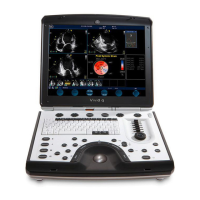
The Vivid i n and Vivid q N keyboard unit comprise the main user-interactive devices: an alphanumeric
keyboard, a 1.5" trackball, and an extended keyboard. In addition, it includes one or more printed circuit
boards (PCBs) designed to carry the various electronic components - these include the keyboards’
controller, TGC potentiometers, USB Hub, and backlight illumination.
Figure 5-26 below shows a high-level functional block diagram of the keyboard unit. The individual
components are described in the Keyboard and Operator Panel Components section, page 5-35.
Figure 5-26 Vivid i n/ Vivid q N Keyboard — Block Diagram
5-7-2 Keyboard and Operator Panel Components
5-7-2-1 Power ON/OFF Button
The Power On/Off button receives 3.3 V from the BEP. Once shorted, this voltage is routed to the
PMC which will activate or perform the appropriate task, as required.
5-7-2-2 Alphanumeric Keyboard
The Vivid i n/ Vivid q N alphanumeric keyboard, with a key arrangement similar to that of a laptop
keyboard, is based on the global GE International standard keyboard requirements.
The alphanumeric keyboard has a PS/2 interface and supports all standard alpha-numeric functionality,
such as, auto-repeat, standard ASCII output codes, etc.
Specially designed, high-quality key caps - together with controllable backlighting - provide a keyboard
that is comfortable and easy to use.
The upper row of functional keys (F1 - F11), are clearly identified as being assigned to specific
ultrasound functions.

 Loading...