GE HEALTHCARE
DIRECTION FQ091013, REVISION 1 VIVID I N AND VIVID Q N SERVICE MANUAL
3-14 Section 3-5 - Preparing for Installation
3-5-3 Component Inspection
After verifying that all the required parts are included in the shipping crate, inspect the system
components using the checklist supplied below. In addition, ensure that all the labels described in
Chapter 1 - Introduction are present, accurate and in good condition, and enter the serial number printed
on the main label into the system installation details card, as described in System Installation Details on
page 3-178.
3-5-3-1 Damage Inspection Checklist
Visually inspect the contents of the shipping carton for damage. If any parts are damaged or missing,
contact an authorized GE Service Representative.
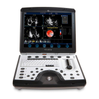
•A Damage Inspection Checklist for the Vivid i n/Vivid q N portable ultrasound scanner is provided
in Table 3-7 below.
•A Damage Inspection Checklist for the SafeLock Cart (optional) is provided in Table 3-8 on
page 3-15.
Table 3-7 Damage Inspection Checklist - Vivid i n/ Vivid q N System
Step Item Recommended Procedure
1
Console
Verify that the system is switched OFF and unplugged. Clean the console and
control panel.
2
Control Console
Physically inspect the control console for missing or damaged items. Verify the
proper illumination of all the control panel buttons.
3
Probes
Check all probes for wear and tear on the lens, cable, and connector. Look for bent
or damaged pins on the connector and in the connector socket on the unit. Verify
that the EMI fingers around the probe connector socket housing are intact. Check
the probe locking mechanism and probe switch.
4
LCD Display
Clean the LCD display by gently wiping with a dry, soft, lint-free non-abrasive
folded cloth. Inspect the monitor for scratches and raster burn.
5
Fans Verify that the system’s cooling fans and peripheral fans are operating.
6
Rear Panel
Check the rear panel connectors for bent pins, loose connections and loose or
missing hardware. Screw all the cable connectors tightly to the connector sockets
on the panel. Verify that the labeling is in good condition.
7
Covers
Check that all screws are tightly secured in place, that there are no dents or
scratches and that no internal parts are exposed.
8
Peripherals
Check and clean the peripherals in accordance with the manufacturer’s directions.
To prevent EMI or system overheating, dress the peripheral cables inside the
peripheral cover.
9
AC DC System
Check the AC DC unit is not damaged or cracked board and verify that the output
cable is properly secured.
10
Power Cord
Check the power cord for cuts, loose hardware, tire marks, exposed insulation, or
any deterioration. Verify continuity. Replace the power cord, as required.
b

 Loading...