GE HEALTHCARE
DIRECTION FQ091013, REVISION 1 VIVID I N AND VIVID Q N SERVICE MANUAL
Chapter 5 - Components and Function (Theory) 5-39
Section 5-8
ECG Module
5-8-1 Overview
The Vivid i n/ Vivid q N ECG Patient I/O module is designed to enable acquisition of the following
signals: ECG and external ECG. The different pins on the ECG input connector are specifically
assigned to support either External ECG or Internal ECG:
• The Internal ECG module supports acquisition of two bipolar ECG channels: leads I, II.
• The External ECG module supports acquisition of a single bipolar ECG input channel ranging
from -1 to +1 volt allowing amplification of 1000. The minimal allowed impedance is 10 M ohm.
The ECG module is located under the keyboard assembly (see Figure 5-6 on page 5-9). All power and
communication is supplied to the ECG module via the USB hub located in the keyboard module as
shown in Figure 5-29 below.
Figure 5-29 ECG Patient I/O Module
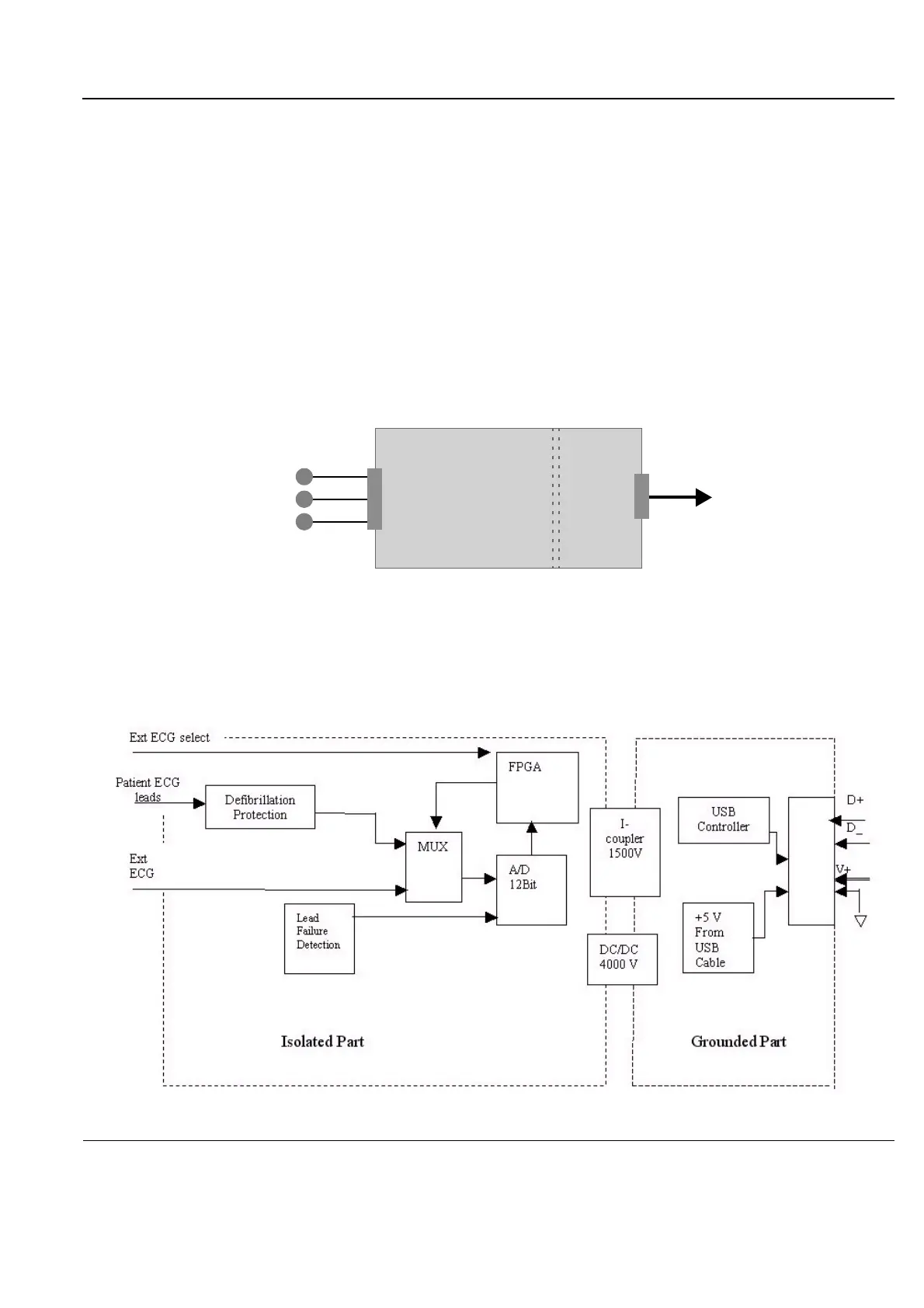
A general block diagram of the ECG Patient I/O Module is shown in Figure 5-30 below.
Figure 5-30 ECG Patient I/O Module - Block Diagram
Rear
Front
Isolated
Grounded
USB
Cable
ECG Input
3 Leads
Part
Part

 Loading...


