6.6 Flicker
106
ΔV10 Flicker Meter
ΔV10 Flicker
The ΔV10 flicker function is calculated using the “perceived flicker
curve” calculation method, which is based on digital Fourier transfor-
mation.
Calculation:
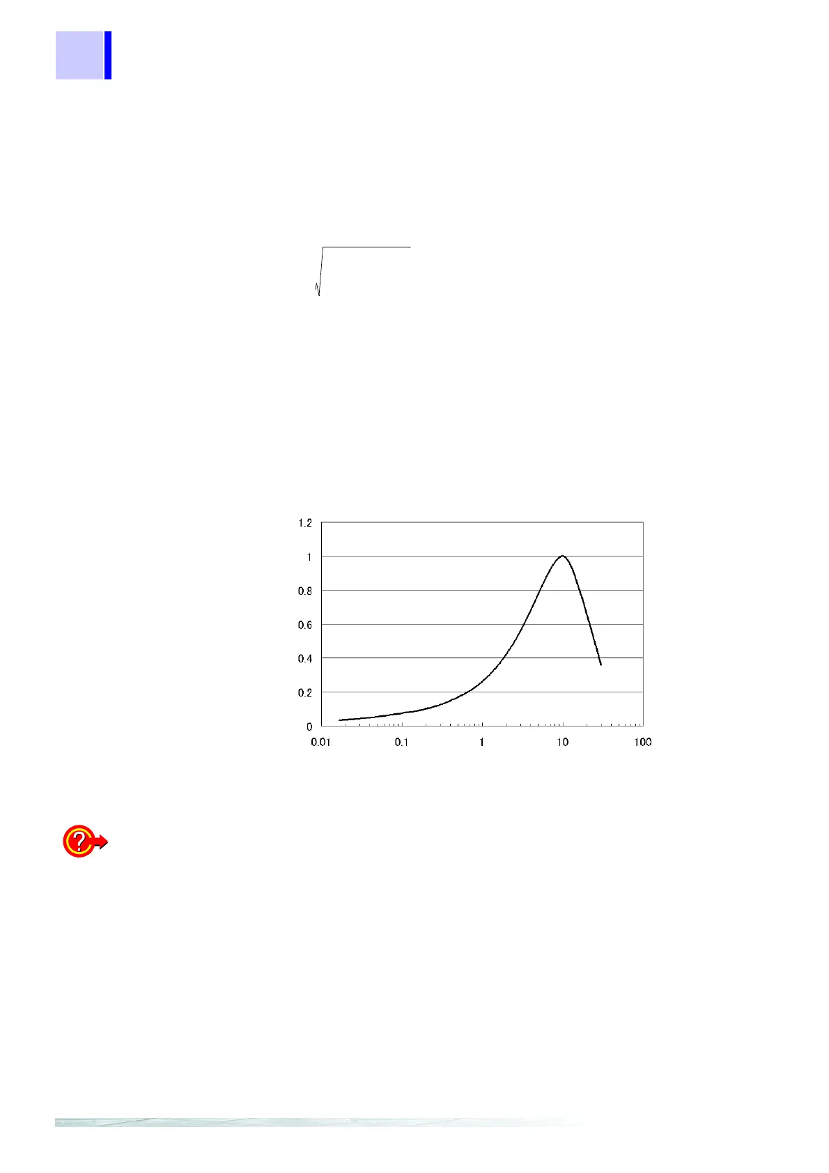
ΔV10 Perceived flicker curve
To measure the
IEC Flicker or ΔV10
Flicker
Set the flicker calculation, voltage recording method, IEC flicker filter,
and ΔV10 flicker measurement channel in SYSTEM - DF2[MEA-
SURE].
❖ Flicker calculation settings (page 56)
❖ Voltage recording method settings (page 56)
❖ IEC flicker filter settings (page 57)
❖ ΔV10 flicker measurement channel settings (page 57)
Δ
V
10
a
n
Δ
V
n
⋅()
2
n1=
∞
∑
=
ΔVn: RMS value [V] for voltage fluctuations in frequency fn.
an: Luminosity coefficient for fn where 10 Hz is 1.0.
(0.05Hz to 30Hz)
Evaluation period:for 1 minute
Frequency[Hz]
ΔV10 Perceived flicker coefficient