ELECTRICAL COMPONENTS
- 321 -
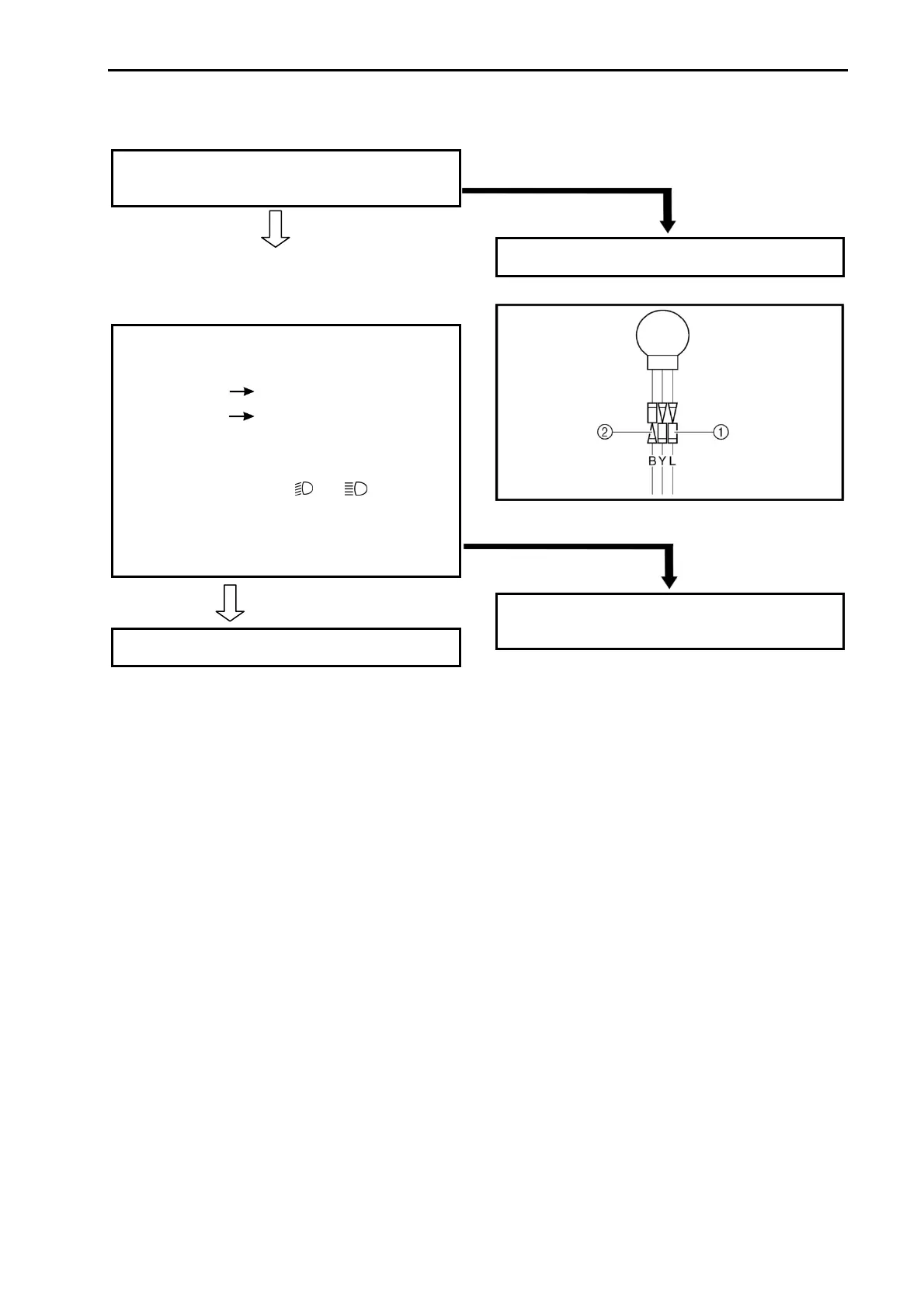
2. If the taillights fail to come on:
(1). Bulb and bulb socket
• Check the bulb and bulb socket for continuity.
CONTINUITY
(2) . Voltage
• Connect the pocket tester (DC 20 V) to the
tail/brake light couplers.
Tester (+) lead
Blue lead terminal ①
Tester (–) lead
Black lead terminal ②
• Turn the main switch to “ON”.
• Turn the light switch to “
” or “ ”.
• Check the voltage (12 V) of the “Blue” lead on
the bulb socket connector.
MEETS SPECIFICATION
This circuit is not faulty.
SIGNALING SYSTEM
Circuit diagram
(See 373 page)
NO CONTINUITY
Replace the bulb and/or bulb socket.
OUT OF SPECIFICATION
The wiring circuit from the main switch to the
bulb socket connector is faulty, repair it.