ELECTRICAL COMPONENTS
- 332 -
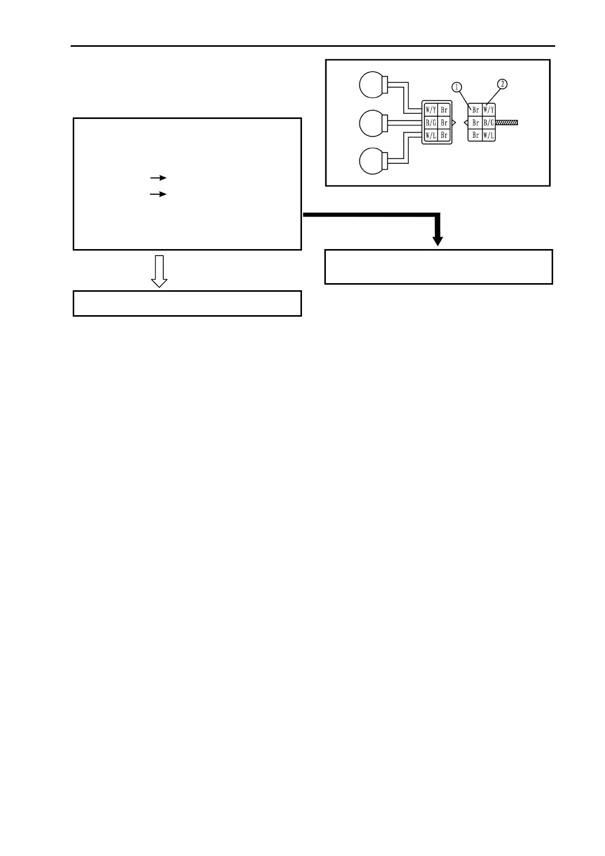
(4).Voltage
• Connect the pocket tester (DC 20 V) to the
indicator light assembly 1 coupler.
Tester (+) lead
Brown terminal ①
Tester (–) lead
White/Yellow terminal ②
• Turn the main switch to “ON”.
• Check the voltage (12 V)
MEETS SPECIFICATION
This circuit is not faulty.
COOLING SYSTEM
Circuit diagram
(See 374 page)
OUT OF SPECIFICATION
The wiring circuit from the main switch to the
bulb socket connector is faulty, repair it.