9 CHANNEL 2.4GHz AIRCRAFT COMPUTER RADIO SYSTEM
Hitec 2.4GHz Maxima Series Receiver
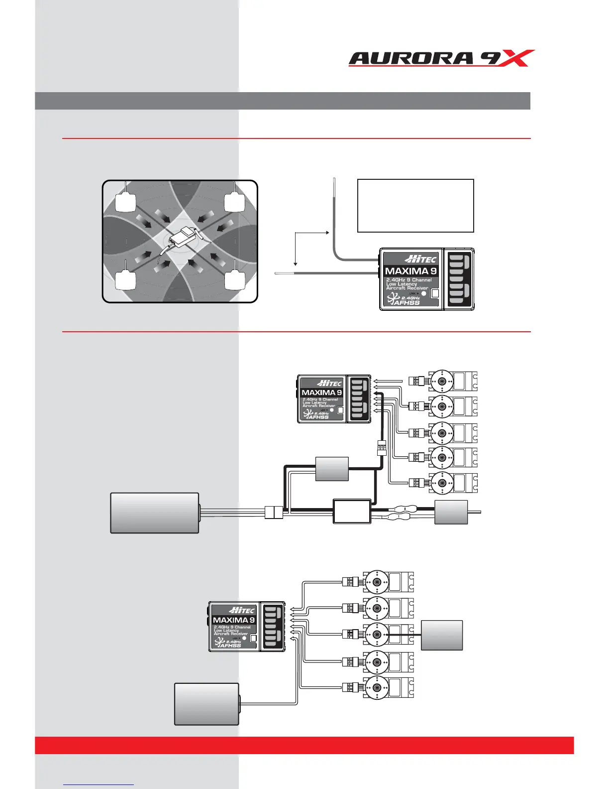
Maxima Series Receiver Antenna Installation
The Maxima receiver series antenna system was created to provide the optimum signal capture capability. Our two antennas must be
installed properly. Refer to the illustration below.
Maxima Series Receiver Connection Diagrams
Electric powered aircraft with Electronic Speed Control
Use this method on electric planes using ESC’s providing power to the receiver and servo functions.
RX
90˚
Recommended installation
method to optimize
receiver performance
CH1
CH2
CH3
CH4
CH5
CH6
CH7
CH8 BAT/9
CH1
CH2
CH3
CH4
CH5
CH6
CH7
CH8 BAT/9
SERVOSERVO SERVO SERVO
Receiver
Battery
SERVO
Engine
CH1
CH2
CH3
CH4
CH5
CH6
CH7
CH8 BAT/9
SERVOSERVO SERVO SERVO
Power Battery
Motor
SERVO
BEC
ESC
Glow, gas or electric powered aircraft using a separate receiver battery supply.
Follow this connection diagram when using a regulated Li-Po, or 4.8 to 6V receiver battery.
15